Site Settings

Warehouses
Language settings
Currency settings
Resources
Video Library
Cx Family Common Mode Chokes
0402CT Low Profile Chip Inductors
XAL7050 High-inductance Shielded Power Inductors
XGL4020 Ultra-low DCR Power Inductors

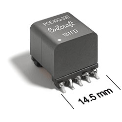
POExxQ High Power Flyback Transformers

for Power over Ethernet

RoHS compliant halogen free AEC-Q flag
  • Developed for Flyback PoE DC/DC Powered Devices (PD) power converters up to 51 W
  • Designed to meet IEEE802.3bt standard and operates with 36 – 57 V input
  • Perfect solution for high power PoE applications including Smart Building and IoT
  • 250 kHz switching frequency
  • AEC-Q200 Grade 1 (-40°C to +125°C)

Buy Now:
Count Unit price
1 $3.31
150 $3.23
300 $2.94
600 $2.68
1200 $2.23
2400 $2.03
5000 $1.85

For high volume or non-stock items, request a quote.

. in stock, ready to ship today.
Request a Sample:

Specifications

Electrical specifications at 25°C.

Part number
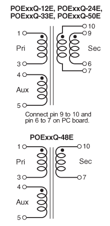
(Hover for schematics)
Power (W) Inductance
at 0A (µH) 1
Tolerance (%) Isat (A) 2 DCR max (mΩ) Leakage
Inductance
max (µH) 3
Turns Ratio Isolation
Voltage (Vrms) 4
Secondary
Output (V, A) 5
Pri Sec Aux Pri : Sec : Aux
POE40Q-33E_ 40 33.3 15 3.5 64.0 2.0 104 0.32 1 : 0.143 : 0.5 1500 3.3 V , 11 A
POE40Q-50E_ 40 33.3 15 3.5 66.0 4.0 102 0.25 1 : 0.214 : 0.5 1500 5 V , 7.3 A
POE40Q-12E_ 40 27.8 15 3.7 35.0 18.0 85.0 0.14 1 : 0.5 : 0.5 1500 12 V , 3 A
POE40Q-24E_ 40 27.8 15 3.7 35.0 69.0 85.0 0.14 1 : 1 : 0.5 1500 24 V , 1.5 A
POE40Q-48E_ 40 27.8 15 3.7 34.0 266 85.0 0.13 1 : 2 : 0.5 1500 48 V , 0.76 A
POE51Q-33E_ 51 26.7 10 4.5 64.0 2.0 104 0.32 1 : 0.143 : 0.5 1500 3.3 V , 14.1 A
POE51Q-50E_ 51 26.7 10 4.5 66.0 4.0 102 0.25 1 : 0.214 : 0.5 1500 5 V , 9.3 A
POE51Q-12E_ 51 22.2 10 4.7 35.0 18.0 85.0 0.14 1 : 0.5 : 0.5 1500 12 V , 3.9 A
POE51Q-24E_ 51 22.2 10 4.7 35.0 69.0 85.0 0.11 1 : 1 : 0.5 1500 24 V , 1.9 A
POE51Q-48E_ 51 22.2 10 4.7 34.0 266 85.0 0.10 1 : 2 : 0.5 1500 48 V , 0.97 A
Notes
  1. Inductance is for the primary, measured at 250 kHz, 0.5 Vrms, 0 Adc.
  2. DC current at 25°C that causes an inductance drop of <15% (POExx51Q) and <15% (POExx40Q) from its value without current.
  3. Leakage inductance is for the primary with the secondary and aux windings shorted.
  4. 1500 Vrms, 1 minute isolation (hipot) between primary and auxillary and auxillary to secondary.
  5. Output is for the secondary. Output of the aux winding is 12 V, 30 mA.

Termination:

  • RoHS-compliant, halogen free. 260°C compatible. Tin-silver-copper over tin over nickel over phos bronze terminations.

Packaging:

  • D = 13″ machine-ready reel. EIA-481 embossed plastic tape (150 parts per full reel). Quantities less than full reel available: in tape (not machine ready) or with leader and trailer ($25 charge).
Environmental
Environmental:
RoHS compliant , halogen free
Ambient temperature range:
–40°C to +125°C
Storage temperature range:
Component: –40°C to +165°C
Tape and reel packaging: –40°C to +80°C
Maximum part temperature:
+165°C (Ambient + temp rise)
Failures in Time (FIT) / Mean Time Between Failures (MTBF):

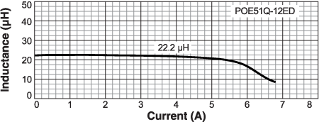
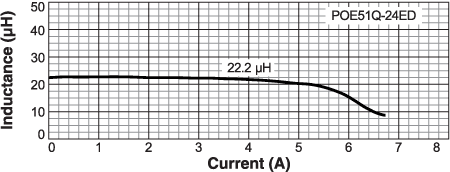
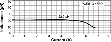
Performance curves

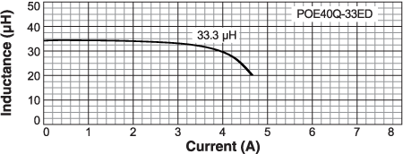
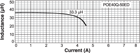
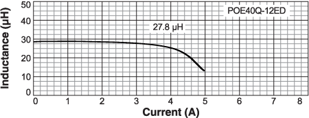
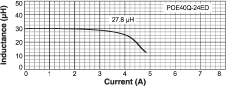
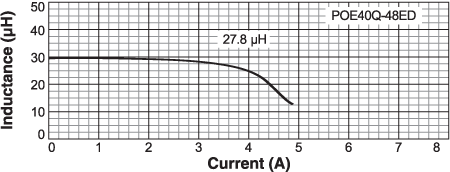
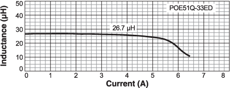
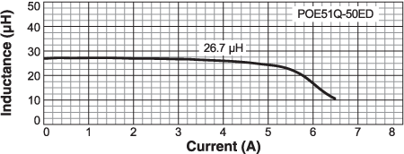
Inductance vs Current

Schematics

poexxqs.gif

Physical characteristics

poexxqd-(2).gif

Tape and Reel specification

tapereel_pl.gif

 
Parts per reel Reel dimensions (mm) Tape dimensions (mm) Orientation
13" (330 mm) A B C D E W P Po P1 H T part_or_c.gif
150 330 100 13 50,4 44,4 44 28 4 2 14,6 0,5
 

General specification

Core Material:
Ferrite
Weight:
6.5 – 8 g

Soldering/Washing

Moisture Sensitivity Level (MSL):
1 (unlimited floor life at <30°C / 85% relative humidity)
Resistance to soldering heat:
Max three 40 second reflows at +260°C, parts cooled to room temperature between cycles
Refer to Soldering Coilcraft Components before soldering.

Related product series