Site Settings

Warehouses
Language settings
Currency settings
Resources
Video Library
Cx Family Common Mode Chokes
0402CT Low Profile Chip Inductors
XAL7050 High-inductance Shielded Power Inductors
XGL4020 Ultra-low DCR Power Inductors

016008C (0402)

Ceramic Chip Inductors

RoHS compliant halogen free
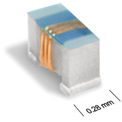
The 016008C Series is the world’s smallest high-frequency-wirewound chip inductors. It features the highest Q factor on the market — up to 40% higher than the best thin-film counterparts. High Q is required to minimize the insertion loss in RF antenna impedance matching circuits, which makes the 016008C ideal for high-frequency applications such as cell phones, wearable devices, and LTE or 5G IoT networks.
  • World’s smallest high-frequency-wirewound chip inductor
  • First metric 0402 (0.4 x 0.2 mm), performance-optimized 01005 size
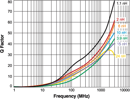
  • Extremely high Q, the highest in the market – higher than all thin film type
  • Exceptionally low DCR – lower than all thin film type
  • 36 inductance values from 0.45 nH to 24 nH

Buy Now:
Count Unit price
1 $1.35
200 $0.95
500 $0.65
1000 $0.53
2500 $0.45
4000 $0.39

For high volume or non-stock items, request a quote.

. in stock, ready to ship today.
Request a Sample:
Designer's Kit:
Kit Values Price
C488 36 (20 of each) $180.00

Specifications

Electrical specifications at 25°C.

Part number Inductance (nH) 1 Tolerance (%) 900 MHz 1.7 GHz 2.4 GHz SRF typ (GHz) 3 DCR max (mΩ) 4 Irms (mA)
Q typ 2 Q typ 2 Q typ 2 at 25°C 5 at 85°C 6 at 125°C 7
016008C-N45XKRW 0.45 10 37 48 59 36.0 60 550 240 140
016008C-N50XKRW 0.5 10 30 40 48 36.0 75 445 170 90
016008C-1N1XKRW 1.1 10 38 50 62 21.0 95 415 240 140
016008C-1N2XKRW 1.2 10 34 45 56 21.3 130 335 170 90
016008C-1N3XKRW 1.3 10 27 37 46 21.0 200 270 120 50
016008C-2N0XJRW 2.0 5 34 45 55 15.2 125 345 240 140
016008C-2N2XJRW 2.2 5 33 45 54 14.8 180 275 170 90
016008C-2N3XJRW 2.3 5 25 36 46 14.8 160 340 190 100
016008C-2N4XJRW 2.4 5 27 36 43 14.2 260 225 120 50
016008C-2N5XJRW 2.5 5 25 35 44 13.6 205 305 170 90
016008C-3N3XJRW 3.3 5 34 45 52 12.2 150 305 240 140
016008C-3N6XJRW 3.6 5 31 42 48 12.0 230 245 170 90
016008C-3N8XJRW 3.8 5 27 36 42 11.4 345 195 120 50
016008C-3N9XJRW 3.9 5 27 37 42 11.3 230 275 190 100
016008C-4N3XJRW 4.3 5 32 42 48 10.8 190 265 240 140
016008C-4N7XJRW 4.7 5 34 47 57 11.0 275 220 170 90
016008C-5N1XJRW 5.1 5 31 42 50 10.0 325 200 140 70
016008C-5N3XJRW 5.3 5 29 40 47 9.7 430 175 120 50
016008C-5N6XJRW 5.6 5 28 39 47 9.8 275 220 190 100
016008C-5N8XJRW 5.8 5 35 48 58 9.8 315 220 190 100
016008C-6N0XJRW 6.0 5 31 42 51 9.8 340 200 170 90
016008C-6N2XJRW 6.2 5 33 44 53 9.7 385 185 140 70
016008C-6N8XJRW 6.8 5 31 42 48 9.0 310 200 190 100
016008C-6N9XJRW 6.9 5 30 40 46 8.8 510 160 120 50
016008C-7N5XJRW 7.5 5 28 37 43 8.2 320 260 190 100
016008C-7N8XJRW 7.8 5 31 42 49 8.4 380 180 170 90
016008C-8N2XJRW 8.2 5 30 40 46 8.1 445 170 140 70
016008C-8N8XJRW 8.8 5 30 39 44 7.8 600 145 120 50
016008C-9N5XJRW 9.5 5 28 37 44 7.6 575 180 140 70
016008C-10NXJRW 10.0 5 31 40 46 7.4 520 155 140 70
016008C-12NXJRW 12.0 5 27 37 42 6.5 640 170 140 70
016008C-13NXJRW 13.0 5 30 38 43 6.5 730 130 120 50
016008C-15NXJRW 15.0 5 27 35 38 6.2 820 120 120 50
016008C-18NXJRW 18.0 5 27 37 42 5.5 1020 120 100 40
016008C-20NXJRW 20.0 5 28 35 37 5.3 1300 110 90 40
016008C-24NXJRW 24.0 5 28 33 33 4.8 1550 100 90 40
Notes
  1. Inductance measured at 250 MHz using a Coilcraft ccf1426 fixture in an Agilent/HP 4287 impedance analyzer with Coilcraft-provided correlation piece
  2. Q measured using an Agilent/HP 4991 with an Coilcraft CCF1481 test fixture.
  3. SRF measured using Agilent/HP 8722ES network analyzer and Coilcraft CCF1406 test fixture.
  4. DCR measured on Cambridge Technology micro-ohmmeter and Coilcraft CCF858 test fixture.
  5. Current that causes a 40°C temperature rise at 25°C ambient. This information is for reference only and does not represent absolute maximum ratings.
  6. Maximum current that can be applied at 85°C.
  7. Maximum current that can be applied at 125°C.

Tolerance:

  • J = 5%, K = 10%

Termination:

  • R =RoHS compliant matte tin over copper over molybdenum - manganese

Packaging:

  • W = 7″ machine-ready reel. EIA-481 punched paper tape (2000 parts per full reel).
Environmental
Environmental:
RoHS compliant , halogen free
Ambient temperature range:
40°C to +125°C with Irms current
Storage temperature range:
Component: –40°C to +140°C.
Tape and reel packaging: –40°C to +80°C
Maximum part temperature:
+140°C (ambient + temp rise).
Failures in Time (FIT) / Mean Time Between Failures (MTBF):

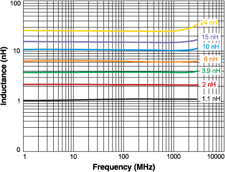
Performance curves

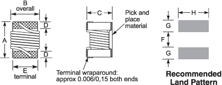
Physical characteristics

016008cd.gif
 
A max B max C max D ref E ref F ref G ref H ref  
0.0185 0.0110 0.0138 0.0035 0.0080 0.0060 0.0090 0.0120 inches
0,47 0,28 0,35 0,09 0,20 0,15 0,23 0,30 mm


Tape and Reel specification

tapereel_pa-(1).gif

 
Parts per reel Reel dimensions (mm) Tape dimensions (mm) Orientation
7" (178 mm) A B C D E W P Po P1 H T part_or_i-(1).gif
2000 178 100 13 14,4 8,4 8 2 4 2 0,38 0,42

General specification

Core Material:
Ceramic
Weight:
0.10 – 0.16 mg
Packaging:
2000 per 7″ reel; Paper tape:  8 mm wide, 0.42 mm thick, 2 mm pocket spacing, 0,38 mm pocket depth
Temperature coefficient of inductance:
+25 to +150 ppm/°C

Soldering/Washing

Moisture Sensitivity Level (MSL):
1 (unlimited floor life at <30°C / 85% relative humidity)
Resistance to soldering heat:
Max three 40 second reflows at +260°C, parts cooled to room temperature between cycles
Refer to Soldering Coilcraft Components before soldering.
PCB Washing:
PCB washing Tested to MIL-STD-202 Method 215 plus an additional aqueous wash. More info