Site Settings
Products
Applications
Resources
Product Documentation
Handling & Processing
Models & Layout Tools


Quality
About


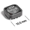
.gif "ja4590d-(1).gif")
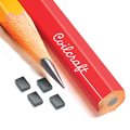
.gif "dims_inches_mm-(1).gif")
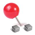
.gif "tapereel_pl-(21).gif")