Site Settings

Warehouses
Language settings
Currency settings
Resources
Video Library
Cx Family Common Mode Chokes
0402CT Low Profile Chip Inductors
Inductors Explained by Coilcraft & Mouser
XGL4020 Ultra-low DCR Power Inductors

MSD1583T Series

Common Mode Chokes

RoHS compliant halogen free
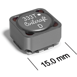
The MSD1583T series high-temperature common mode chokes deliver both common-mode and differential-mode filtering in a single device. They are ideal for power line and signal line applications, offering 500 Vrms one-minute winding-to-winding isolation.
  • Only 8.6 mm high and 15 mm square
  • Ideal for use in both power line and signal line applications
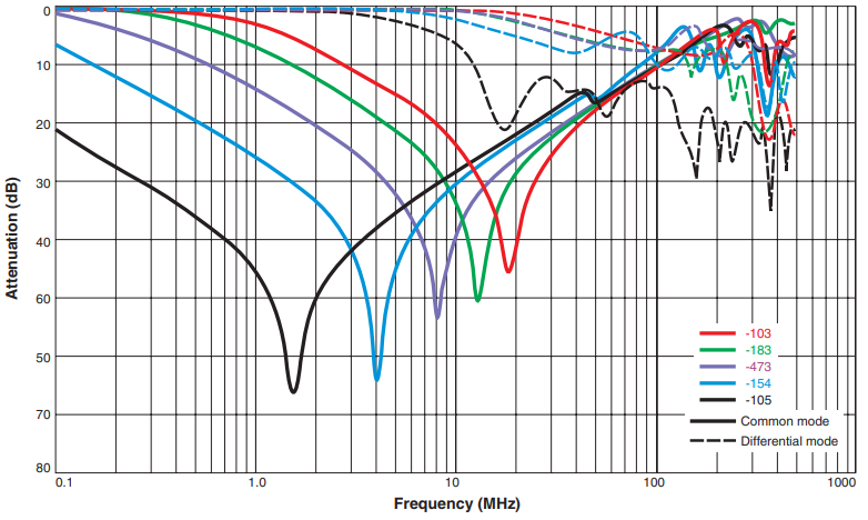
  • Common- and differential-mode filtering in a single device
  • Up to 38 MHz differential mode cutoff frequency
  • Can be used as coupled inductors for SEPIC applications
Refer to Designing Common Mode Filters for design guidance.

Buy Now:

The part number you have selected is not available through our online store.

Please click the "Request Quote" button for pricing and more information.

. in stock, ready to ship today.
Request a Sample:

Specifications

Electrical specifications at 25°C.

Part number 1 Lines Common mode
peak impedance (kΩ)
Cutoff
frequency (MHz) 2
Inductance
min (µH) 3
Irms (A) 4 DCR max (Ω) 5 Isolation
Voltage (Vrms) 6
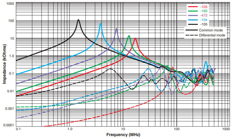
MSD1583T-103MED 2 10.86 @ 17.0 MHz 38.0 8.0 3.68 0.031 500
MSD1583T-123MED 2 12.11 @ 16.0 MHz 30.0 9.6 3.54 0.037 500
MSD1583T-153MED 2 12.31 @ 14.0 MHz 25.0 12 3.18 0.045 500
MSD1583T-183MED 2 15.77 @ 13.0 MHz 25.0 14 3.04 0.048 500
MSD1583T-223MED 2 14.47 @ 12.0 MHz 28.0 18 2.44 0.065 500
MSD1583T-333MED 2 33.82 @ 9.0 MHz 28.0 26 2.16 0.095 500
MSD1583T-473MED 2 39.79 @ 7.6 MHz 23.0 38 1.98 0.115 500
MSD1583T-683MED 2 49.24 @ 5.9 MHz 17.0 54 1.56 0.165 500
MSD1583T-104KED 2 69.83 @ 5.0 MHz 16.0 90 1.24 0.26 500
MSD1583T-154KED 2 73.09 @ 3.9 MHz 12.0 135 1.06 0.38 500
MSD1583T-224KED 2 78.91 @ 3.3 MHz 9.7 198 0.92 0.46 500
MSD1583T-474KED 2 104.90 @ 2.2 MHz 7.4 423 0.65 1.04 500
MSD1583T-105KED 2 129.00 @ 1.5 MHz 5.8 900 0.42 2.4 500
Notes
  1. When ordering, please specify termination code: e.g. MSD1583T-105KED
  2. Frequency at which the differential mode attenuation equals 3 dB.
  3. Inductance shown for each winding, measured at 100 kHz, 0.1 Vrms, 0 Adc on an Agilent/HP 4284A LCR meter or equivalent.
  4. Irms: Current that causes a 40°C temperature rise from 25°C ambient. This information is for reference only and does not represent absolute maximum ratings.
  5. DCR is for each winding, measured at 25°C. For other operating temperatures, use this DCR at Temperature calculator.
  6. Interwinding isolation (hipot) tested for one minute.

Termination:

  • E = RoHS compliant matte tin over nickel over phos bronze.
  • Q = RoHS tin-silver-copper (95.5/4/0.5). (Special order, added cost)
  • P = non-RoHS tin-lead (63/37). (Special order, added cost)

Packaging:

  • D = 13″ machine-ready reel. EIA-481 embossed plastic tape (300 parts per full reel). Quantities less than full reel available: in tape (not machine ready) or with leader and trailer ($25 charge).
Environmental
Environmental:
RoHS compliant , halogen free
Ambient temperature range:
–40°C to +125°C with Irms current
Storage temperature range:
Component: –40°C to +165°C.
Tape and reel packaging: –40°C to +80°C
Maximum part temperature:
+165°C (ambient + temp rise)
Failures in Time (FIT) / Mean Time Between Failures (MTBF):

Performance curves

Typical Attenuation (Ref: 50 Ohms)

Typical Impedance vs Frequency

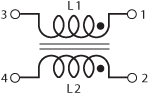
Schematics

msd1583t_cms.gif

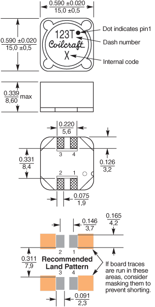
Physical characteristics

msd1583t_cmd.gif

dims_inches_mm.gif

Tape and Reel specification

tapereel_pl.gif


Parts per reel Reel dimensions (mm) Tape dimensions (mm) Orientation
13" (330 mm) A B C D E W P Po P1 H T part_or_ak.gif
300 330 100 13 38,4 32,4 32 24 4 2 8,6 0,5

General specification

Core Material:
Ferrite
Weight:
3.7 – 4.4 g
Packaging:
Packaging 300/13″ reel; Plastic tape: 32 mm wide, 0.5 mm thick, 24 mm pocket spacing, 8.6 mm pocket depth
Winding to Winding Isolation:
500 Vrms, one minute

Soldering/Washing

Moisture Sensitivity Level (MSL):
1 (unlimited floor life at <30°C / 85% relative humidity)
Resistance to soldering heat:
Max three 40 second reflows at +260°C, parts cooled to room temperature between cycles
Refer to Soldering Coilcraft Components before soldering.
PCB Washing:
Tested to MIL-STD-202 Method 215 plus an additional aqueous wash. More info.

Related product series