Site Settings

Warehouses
Language settings
Currency settings
Resources
Video Library
Cx Family Common Mode Chokes
0402CT Low Profile Chip Inductors
XAL7050 High-inductance Shielded Power Inductors
XGL4020 Ultra-low DCR Power Inductors

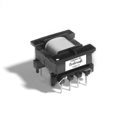
Flyback Transformers

for ON Semiconductor NCP1200

RoHS compliant
  • Developed for use with the ON Semiconductor NCP1200 PWM Current-Mode Controller
  • Designed for use in flyback power supplies
  • Universal line voltage, 85 – 265 VAC
  • Custom versions available

Buy Now:
Count Unit price
1 $6.15
250 $5.98
500 $5.44
1000 $4.94
2500 $4.49
5000 $4.09

For high volume or non-stock items, request a quote.

. in stock, ready to ship today.
Request a Sample:

Typical Application

Works with ON Semiconductor NCP1201

Part number AC Input Voltage Output Power Fsw
Sec Aux
Y8844-AL 85 V 265 V 6.5 V , 0.54 A - 3.5 W 100 kHz
Y8848-AL 85 V 265 V 12 V , 0.83 A - 10 W 100 kHz
Z9007-BL 85 V 265 V 16 V , 4.2 A - 67 W 100 kHz
Z9260-AL 85 V 265 V 16 V , 4.2 A 15 V , 0.2 A 67 W 100 kHz

Specifications

Electrical specifications at 25°C.

Part number
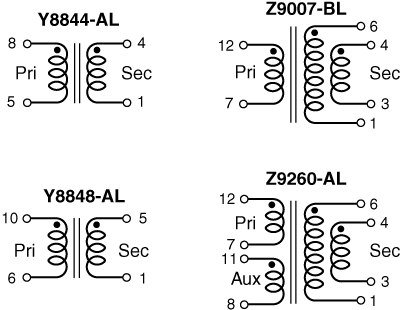
(Hover for schematics)
Inductance
at 0A (mH) 1
(Tolerance: ±10%)
DCR max (Ω) Leakage
Inductance
max (µH) 2
Turns Ratio 3 Isolation
Voltage (Vrms) 4
Pri Sec Aux Pri : Sec : Aux
Y8844-AL 2.9 4.250 0.070 - 80 1 : 0.08 : - 1500
Y8848-AL 1.8 1.770 0.038 - 60 1 : 0.1 : - 2000
Z9007-BL 0.7 0.261 0.007 - 16 1 : 0.16 : - 1500
Z9260-AL 0.7 0.261 0.007 0.045 26 1 : 0.16 : 0.15 2000
Notes
  1. Inductance is for the primary, measured at 10 kHz, 0.1 Vrms, 0 Adc
  2. Leakage inductance tested at 100 kHz, 0.1 Vrms
  3. Primary to secondary turns ratio specified with secondary windings connected in parallel.
  4. Isolation tested between primary and secondary on all parts and between primary and auxiliary on Z9260-AL.

Termination:

  • RoHS-compliant. Tin-silver over tin over copper.
Environmental
Environmental:
RoHS compliant
Ambient temperature range:
-40°C to +85°C
Storage temperature range:
Component: −40°C to +85°C
Tape and reel packaging: −40°C to +80°C
Failures in Time (FIT) / Mean Time Between Failures (MTBF):

Schematics

y8844s.gif

For Z9007-BL and Z9260-AL, secondary windings to be connected in parallel on the circuit board.

Physical characteristics

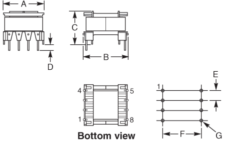
​Y8844-AL


y8844d.gif
 
A max B max C max D min E F G dia
0.72 0.79 0.55 0.118 0.150 0.600 0.030 inches
18,3 20,1 14,0 3,0 3,81 15,24 0,76 mm


Y8848-AL

y8844d-(1).gif
 
A max B max C max D min E F G dia H (1 place)
1.10 1.10 0.95 0.12 0.200 0.620 0.044 0.150 inches
27,9 27,9 24,1 3,05 5,08 15,75 1,12 3,81 mm
 

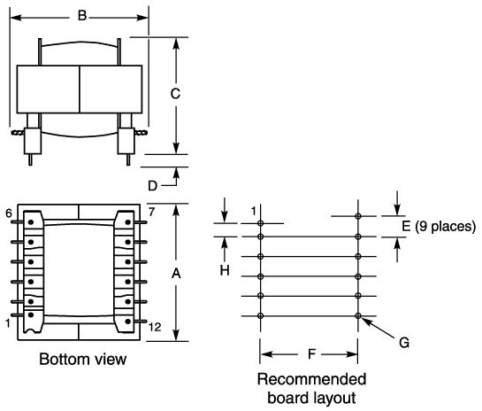
Z9007-BL, Z9260-AL

z9007d.gif
 
A max B max C max D min E F G dia H (1 place)
1.45 1.45 1.17 0.12 0.200 0.875 0.044 0.150 inches
36,8 36,8 29,7 3,05 5,08 22,2 1,12 3,81 mm

General specification

Weight:
Y8844: 6.7 g; Y8848: 16 g; Z9007: 52 g: Z9260: 54 g
Packaging:

Y8844 = 49 per tray
Y8848 = 30 per tray
Z9007/Z9260 = 25 per tray

Washing

PCB Washing:
Tested to MIL-STD-202 Method 215 plus an additional aqueous wash. More info.