Site Settings

Warehouses
Language settings
Currency settings
Resources
Video Library
Cx Family Common Mode Chokes
0402CT Low Profile Chip Inductors
Inductors Explained by Coilcraft & Mouser
XGL4020 Ultra-low DCR Power Inductors

ZG3504-BE Pulse Transformer

For isolated gate driver bias supply

RoHS compliant halogen free AEC-Q flag
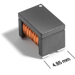
The ZG3504-BE series pulse transformer feature low interwinding capacitance to minimize EMI and deliver exceptionally high Common Mode Transient Immunity (CMTI), making them ideal for On-Board Chargers (OBCs), DC-DC converters, and traction inverters. Designed for high-power reliability and fully AEC-Q200 qualified, this series ensures robust performance under the rigorous electrical, thermal, and vibration conditions of modern electric vehicle systems.
  • Optimized for QFN AHV85003/043 chipset by Allegro MicroSystems
  • Ideal for isolated power supplies in data center, automotive OBC, and industrial applications
  • Low interwinding capacitance to minimize EMI and achieve high CMTI
  • AEC-Q200 qualified

Buy Now:

The part number you have selected is not available through our online store.

Please click the "Request Quote" button for pricing and more information.

. in stock, ready to ship today.
Request a Sample:

Specifications

Electrical specifications at 25°C.

Part number 1
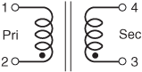
(Hover for schematics)
Inductance
at 0A (µH) 2
(Tolerance: ±25%)
DCR max 3 Leakage
Inductance
±25% (µH) 4
Turns Ratio Capacitance
max (pF) 5
Isolation
Voltage (Vrms) 6
Pri (Ω) Sec (Ω) Pri : Sec
ZG3504-BEC 7.2 0.11 0.32 0.14 1 : 3 4 2800
Notes
  1. When ordering, please specify packaging code: e.g. ZG3504-BEC
  2. Inductance measured at 1 MHz, 0.1 Vrms, 0 ADC on an Agilent 4263B (or equivalent).
  3. DCR is measured on a Keithley 580 Micro-ohmmeter (or equivalent)
  4. Leakage Inductance LL is measured at 1 MHz, 0.1 Vrms on an Agilent 4263B (or equivalent) with pins 3, 4 shorted.
  5. Interwinding capacitance is measured from primary to secondary at 250 KHz, 0.1 Vrms.
  6. 2800 Vrms, 4000 VDC; one minute isolation (hipot) measured between primary and secondary. 4.9 mm creepage and clearance Material Group IIIa (175 ≤ CTI < 400).
Designed to meet the following requirements. Please contact [email protected] for questions about suitability for use in other application conditions.
 

Example 1*
Reinforced insulation example

Example 2*
Basic insulation example
Example 3
Basic insulation example
Working voltage 240 V Working voltage 600 V Working voltage 490 V
Altitude 5000 m Altitude 5000 m Altitude 5000 m
Overvoltage category II Overvoltage category II Overvoltage category II
Pollution degree 2 Pollution degree 2 Pollution degree 2
 
The transformer contains 7 mm creepage and 4.9 mm clearance between primary and secondary windings with Material Group IIIa (175 ≤ CTI < 400).

* For examples 1 and 2, Material Group I PCB is needed. If using Material Group IIIa or IIIb PCB, a groove is needed between primary and secondary pads in order to maintain the transformer’s 8 mm creepage when mounted.


Termination:

  • E = RoHS compliant tin over nickel over silver glass frit.

Packaging:

  • 7" reel, machine-ready 
    EIA-481 embossed plastic tape. (350 per full reel). Quantities less than full reel available: in tape (not machine ready) or with leader and trailer ($25 charge).
  • 13" reel, machine-ready 
    EIA-481 embossed plastic tape. Factory order only, not stocked (1500 parts per full reel).
Environmental
Environmental:
RoHS compliant , halogen free
Ambient temperature range:
–40°C to +125°C
Storage temperature range:
Component: –40°C to +140°C
Tape and reel packaging: –40°C to +80°C
Maximum part temperature:
+140°C
Failures in Time (FIT) / Mean Time Between Failures (MTBF):

Schematics

zg3504s.gif

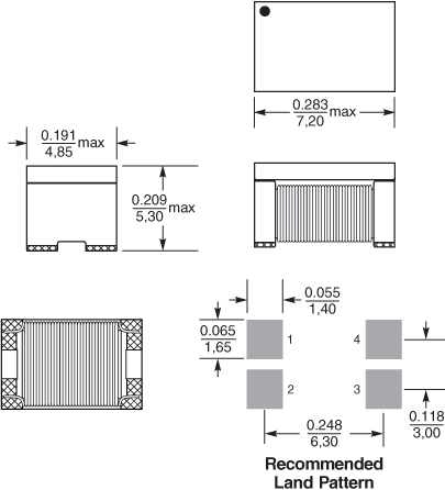
Physical characteristics

zg3504d.gif

dims_inches_mm.gif
 

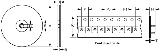
Tape and Reel specification

tapereel_pl.gif
 
Parts per reel Reel dimensions (mm) Tape dimensions (mm) Orientation
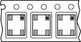
7" (178 mm) 13" (330 mm) A B C D E W P Po P1 H T part_or_cg.jpg
350 1500* 178/330 60/100 13 22,4 16,4 16 8 4 2 5,5 0,40
* Special order

General specification

Core Material:
Ferrite
Weight:
0.53 – 0.54 g
Packaging:
350/7″ reel; 1500/13″ reel Plastic tape: 16 mm wide, 0.4 mm thick, 8 mm pocket spacing, 5.5 mm pocket depth

Soldering/Washing

Moisture Sensitivity Level (MSL):
1 (unlimited floor life at <30°C / 85% relative humidity)
Resistance to soldering heat:
Max three 40 second reflows at +260°C, parts cooled to room temperature between cycles
Refer to Soldering Coilcraft Components before soldering.
PCB Washing:
Tested with pure water or alcohol only. More info.