Site Settings

Warehouses
Language settings
Currency settings
Resources
Video Library
Cx Family Common Mode Chokes
0402CT Low Profile Chip Inductors
XAL7050 High-inductance Shielded Power Inductors
XGL4020 Ultra-low DCR Power Inductors

What is an LC Filter?

LC-Filters_schem2.png
Example: Low-Pass LC Filter Schematic

What is an LC Filter?

An LC filter combines inductors (L) and capacitors (C) to form low-pass, high-pass, multiplexer, band-pass, or band-reject filtering in radio frequency (RF) and many other applications. Passive electronic LC filters block, or reduce, noise (EMI) from circuits and systems, and separate, or condition, desired signals.

While ideal filters would pass desired signal frequencies with no insertion loss or distortion, and completely block all signals in the stop-band, real filters have DC and AC resistances that contribute to insertion loss, requiring careful component selection. Selecting the exact values of the parts for a particular application requires high quality components as well as complete specifications and performance models. The simplest to design and implement are the low-pass and high-pass types.

Coilcraft high-Q, tight-tolerance, surface-mount RF chip inductors and air-core inductors help you achieve top performance in all of these LC filter categories.

How do you design LC filters?

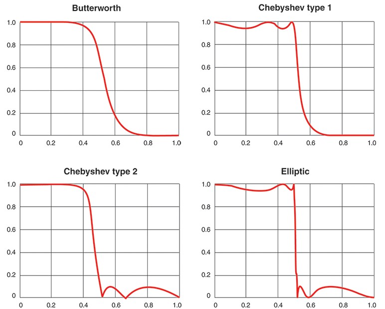
The alignment (type) of the filter determines the flatness of frequency behavior and the sharpness of the cut-off. There are many types of alignments, including those with the most commonly desired characteristics such as Butterworth, Bessel, Chebyshev, and elliptic.

The simplest LC filter consists of one inductor and one capacitor. Higher-order filter alignments use more components to give a sharper, more defined roll-off in attenuation of unwanted noise. For example, Elliptic (Cauer) filters give the sharpest roll-off and are the least sensitive to component variation. As a trade-off, there is more pass-band ripple and stop-band ripple in Elliptic LC filters.

For more details on the various filter alignments shown in Appendix A of this application note.

appendixA.jpg
Appendix A: Passive LC Filter Design and Analysis Filter Alignments and Properties

Modern circuit synthesis and analysis programs can quickly perform the otherwise tedious and time-consuming calculations for designing LC filters. Filter synthesis programs generate the required inductance (L) and capacitance (C) values. Analysis programs simulate the results after the user enters the appropriate values. Once the initial ideal values have been calculated, practical solutions are created using off-the-shelf components.

Ideally, one could simply define the band of frequencies to be passed and those to be blocked, and a program would generate standard component values resulting in the actual on-board performance. Realistically, a passive LC filter design starts with calculations and then a very iterative trial-and-error process is needed to match the actual performance to the required performance. To speed design time and improve accuracy of design calculations, models of real-world inductors are available.

For many designs, accurate inductance models based on actual component measurements are necessary, but ideal capacitors can be used for the simulation. Simulations of filters near the Gigahertz range may require non-ideal capacitor models as well.

Free programs for generating basic LC filter designs are available. Coilcraft's LC Low Pass Filter Designer software by Nuhertz uses real measurement-based s-parameter models of the inductors for improved filter simulations.

How do you design low-pass filters with Coilcraft LC filter Designer Software (Nuhertz Technologies FilterSolutions®)?

While these simulations may be acceptable for many designs, it should be noted they do not include PCB parasitics, which have an effect on the actual cut-off frequency of the components mounted on any PCB.

Ideal component values generated by simulation programs can be used as a good starting point for filter designs, however, if all component and PCB parasitics are ignored the results may not be very close to real-world performance. This can result in a time-consuming process of tuning and adjusting, particularly for high-cutoff-frequency filters.

For high-performance design examples, including component parasitic effects and parasitic interactions of the components on a ceramic circuit board, try the following Coilcraft LC filter reference designs.

Designing low-pass and high-pass filters with Coilcraft LC Filter Reference Designs

These reference designs include 3rd-order Butterworth low-pass and high-pass, as well as 7th order-elliptic filters, and demonstrate the high performance that can be achieved using Coilcraft inductors and standard capacitors.

The 3rd-order low-pass filters reference designs provide a wide range of cut-off frequencies from 3 MHz to 3 GHz. For 3-pole high-pass filters, 15 MHz to 900 MHz cutoff frequencies are achievable.

Compared to a Butterworth filter, elliptic filters have equalized ripple in both the pass-band and the stop-band. However, for the same order level, elliptic has the fastest transition between passband and the stop-band. Coilcraft offers 7th-order elliptic reference designs with less than 0.3 dB insertion loss at 50-Ohm characteristic impedance. These include our off-the-shelf 1812LS Series ferrite chip inductors with tolerances is as low as 5%. These 7th-order-elliptic low-pass filters offer sharp roll-off rate at 80 dB/dec and a wide range of cutoff frequencies from 0.3 MHz to 500 MHz.

Coilcraft LC filter reference designs can save you time, effort and cost, allowing you to better select the right components, evaluate real performance compared to calculations, and achieve your desired results.

In what applications are LC filters used?

LC low-pass and LC high-pass filters are used in many general filtering applications to block undesired frequencies and meet EMC / EMI requirements. They are also used in the following specific applications:

Reference Design for 9th-order elliptical filter for MoCA® applications

This reference design for a 9th-order elliptical filter for MoCA® applications shows a real-world example of a high order sharp cut-off elliptical filter using Coilcraft RF air core inductors.

The Coilcraft Micro Spring™ air core inductors used in this design provide the high performance needed for MoCA filters. The combination of inductance values and performance make these off-the-shelf inductors ideal for the implementation of these filters in set top boxes and cable modems. With tolerances as tight as 1%, there is no longer a need to tune these filters.

Class-D Amplifiers

In order to achieve EMC requirements in Class-D amplifiers above 10 W of output power, an LC filter is used on the output of the amplifier to smooth out the current ripple due to switching . Dual inductors combine two Class-D inductors in a single package to achieve the smallest possible footprint. High-temperature, AEC-Q200 Grade 1 Class-D dual inductors are appropriate for the harsh conditions of automotive applications.

These Class-D inductors from Coilcraft are designed specifically for applications up to 100 W.

Related Application Notes

Coilcraft LC Filter Reference Design

Passive LC Filter Design and Analysis

Designing a 9th Order Elliptical Filter for MoCA® Applications

Designer's Kits

Surface mount RF Inductors

What's Next?

View more: Getting Started Series