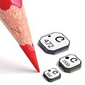
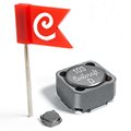
LPS6225 Series Low Profile
Shielded Power Inductors
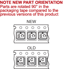
This is a new halogen free version recommended for new designs. Only the termination material, part number, and orientation in the packing tape have changed. The previous version is available only to current customers. |
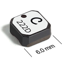
- Compact, low profile shielded power inductor - only 2,5 mm
high, 6,2 mm square
- Handles current up to 5.4 Amps!
- Ideal for high-density applications
- AEC-Q200 Grade 1 (−40°C to +125°C)
- RoHS-compliant, halogen free. 260°C compatible. Matte tin over nickel over silver terminations
- COTS Plus tin-silver-copper and tin-lead terminations available
- Samples of all values are available in Coilcraft Designer's Kit C349
- Need parts for space, military or other critical applications?
See Coilcraft CPS 486PJB series.
Pricing
PDF data sheet
SPECIFICATIONS
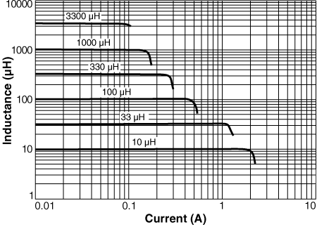
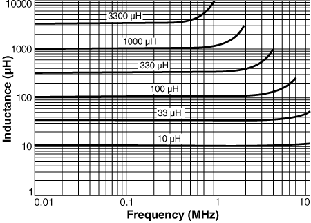
L vs Frequency L vs Current Core loss SPICE models
Dimensions
Tape and reel specifications
3D model
1 |
When
ordering, please specify termination and packaging codes: e.g. LPS6225-106MRC |
|
Termination: |
R = Matte tin over nickel over silver
Special order, added cost: Q = RoHS tin-silver-copper (95.5/4/0.5) or
P = non-RoHS tin-lead (63/37). |
|
Packaging:
|
C = 7"
machine-ready reel
EIA-481 embossed plastic tape 750 parts per full reel).
B = Less than full reel
In tape, but not machine-ready. To have a leader and trailer added ($25 charge),
use code letter C instead.
D = 13" machine-ready reel
EIA-481 embossed plastic tape. Factory order only, not stocked (2500 parts
per full reel). |
2 |
Inductance tested at 100 kHz, 0.1 Vrms, 0 Adc using an Agilent/HP
4192A impedance analyzer or equivalent. |
3 |
DCR measured at 25°C on a
micro-ohmmeter. For other operating temperatures, use this calculator. |
4 |
SRF measured using
an Agilent/HP 8753ES or equivalent. |
5 |
Isat: DC current at which the inductance drops the specified amount from its value without current. Details |
6 |
Irms: Current that causes the specified temperature rise from 25°C ambient. This information is for reference only and does not represent absolute maximum ratings. Temperature derating curves. |
7 |
Ambient temperature range: |
−40°C to +85°C with (40°C rise) Irms Derating curves |
8 |
Storage temperature range: |
Component: −40°C to +125°C
Tape and reel packaging: −40°C to +80°C |
9 |
Maximum part temperature: +125°C (Ambient + temperature rise) |
10 |
Resistance to soldering heat:
Three reflows at >217°C for 90 seconds (+260°C ±5°C for 20 – 40 seconds), allowing parts to cool to room temperature between. |
11 |
Electrical specifications at 25°C. |
Refer to Soldering Coilcraft Components before soldering. |
PCB washing: Tested to MIL-STD-202 Method 215 plus an additional aqueous wash. More info. |
 |
|
|