|
|||
|
Power Magnetics Tools
RF Inductor Tools
CM Choke \ Ferrite Beads
LC Filter Designer IC / Inductor Match Tool Application Notes Other Resources
Designer's Kits
|
|
Part number1 Click to get parts |
Inductance at 0 A2 ±10% (µH) |
Inductance at Ipk3 min (µH) |
DCR max4 (Ohms) |
Leakage inductance5 max (µH) |
Turns ratio | Ipk3 (A) |
Output6 | ||
---|---|---|---|---|---|---|---|---|---|
pri : sec | pri : bias | ||||||||
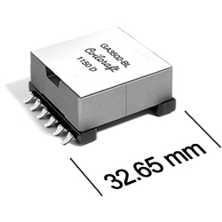
GA3502-BL | 800 | 720 |
pri: sec: bias: |
1.283 0.361 0.146 |
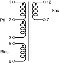
6.60 | 1 : 0.35 | 1 : 0.06 | 0.75 | 110 V, 0.4 A |
1 | When ordering, please specify termination code: e.g. GA3502-BL | |
Termination: | L = RoHS compliant tin-silver over tin over nickel over phos bronze Special order, added cost: T = RoHS tin-silver-copper (95.5/4/0.5) or S = non-RoHS tin-lead (63/37). |
2 | Inductance is for the primary (pins 1 – 3), measured at 250 kHz, 0.3 Vrms. | |
3 | Ipk: Peak primary current drawn at minimum input voltage. | |
4 | DCR for the primary is measured from pin 1 to pin 3.DCR measured at 25°C. For other operating temperatures, use this DCR at Temperature calculator. | |
5 | Leakage inductance is for the primary winding (pins 1 – 3) with the secondary windings shorted. | |
6 | Output is for the secondary. Bias winding output is 18 V, 20 mA. | |
7 | Ambient temperature range: | −40°C to +125°C |
8 | Storage temperature range: | Component: −40°C to +125°C Packaging trays: −40°C to +80°C |
9 | Electrical specifications at 25°C. | |
Refer to Soldering Coilcraft Components before soldering. | ||
PCB washing: Tested to MIL-STD-202 Method 215 plus an additional aqueous wash. More info. | ||
![]() |
Home | Design Tools | Samples | Kits | Price + Stock | Sales | Support | Jobs | Index | |
Your comments and suggestions are welcome. Contact [email protected] Copyright © 2019, Coilcraft, Inc. Privacy policy Updated: August 31, 2018 |
![]() ![]() ![]() |