Website-Einstellungen
Produkte
Automobiltechnik
Informationsmaterial
Produktdokumentation
Handhabung und Verarbeitung
Modelle und Layout-Tools
Kurse/Schulung


Quality
Über


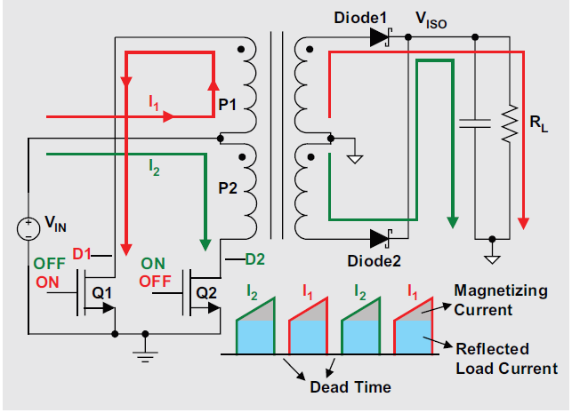.png "Push-pull-current-paths-waveforms-(1).png")
.png "SN6501-(2).png")