
LTspice is a high performance SPICE simulator that simplifies the design of switching regulators. The software is provided free by Analog Devices. LTspice includes a library of basic models for a limited number of Coilcraft inductor models. These models are included in the standard inductor library and are updated periodically.
Coilcraft also offers an easy to install and use advanced model library that can be downloaded from the LTspice library page linked to the right. Installation and usage instructions for these libraries can be found on the same page.
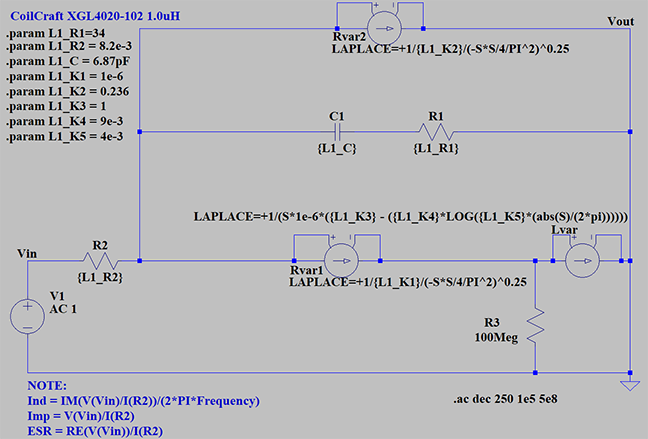
The schematic below is the model structure of the Coilcraft advanced power inductor model. This may differ slightly between series and is different from the RF or Transmission line models.

Depending on the inductor series, the advanced SPICE models may include a variable inductor element, variable series resistance (Rvar1) to model skin effect, a resistor element in series with the parallel capacitance (R1) to limit impedance at resonance, and a variable parallel resistance (Rvar2) to model frequency-dependent low power core losses.
The schematic, element values, and coefficients for variable elements are provided in the PSPICE model document for each inductor series.
The GLaplace component is used in SPICE to describe a frequency-dependent impedance or resistance. Each frequency-dependent element (Rvar1, Rvar2, Lvar) is modeled in LTspice using the GLaplace G2 voltage dependent current source.
Foruse LAPLACE=+1/{L1_K1}/(-S*S/4/PI^2)^0.25 For
use LAPLACE=+1/{L1_K2}/(-S*S/4/PI^2)^0.25 For
use LAPLACE=+1/(S*1e-6*({L1_K3} - ({L1_K4}*LOG({L1_K5}*(abs(S)/(2*pi))))))
The schematic below uses the Coilcraft XGL4020-102 as an example:
.png "LTspiceExampleSchematic-(1).png")
* Coilcraft XGL4020-102 1.0uH
V1 Vin 0 AC 1
R2 N001 Vin {L1_R2}
R1 0 N002 {L1_R1}
C1 N002 N001 {L1_C}
G§Rvar1 N001 0 N001 0 LAPLACE=+1/{L1_K2}/(-S*S/4/PI^2)^0.25
G§Rvar2 N001 N003 N001 N003 LAPLACE=+1/{L1_K1}/(-S*S/4/PI^2)^0.25
G§Lvar1 N003 0 N003 0 LAPLACE=+1/(S*1e-6*({L1_K3}-({L1_K4}*LOG({L1_K5}*(abs(S)/(2*pi))))))
R3 N003 0 100Meg
.param L1_R1 = 34
.param L1_R2 = 8.2e-3
.param L1_C= 6.87pF
.param L1_K1 = 1e-6
.param L1_K2 = 0.236
.param L1_K3=1
.param L1_K4 = 9e-3
.param L1_K5 = 4e-3
.ac dec 250 1e5 5e8
* NOTE: \nInd   = IM(V(Vin)/I(R2))/(2*PI*Frequency)\nImp  = V(Vin)/I(R2)\nESR= RE(V(Vin)/I(R2))
.backanno
.end
When running simulations, note the upper and lower frequency limits for which the model is valid. This information is shown on the Coilcraft SPICE model document for each inductor series.
Im(V(Vin)/I(R2))/(2*pi*frequency)To plot Impedance vs frequency (best viewed in Bode Logarithmic form):
V(Vin)/I(R2)To plot ESR vs frequency (best viewed Bode Logarithmic form):
Re(V(Vin)/I(R2))To plot Q factor vs frequency (best viewed in Cartesian form):
ABS(Im(V(n001)/I(R2))/Re(V(n001)/I(R2)))*note voltage node names may be different it is up to user to ensure voltage is across inductor


