SPICE (Simulation Program with Integrated Circuit Emphasis) was initially developed to mathematically predict integrated circuit behavior. It is also used to predict the effects of passive components, such as resistors (R), inductors (L), and capacitors (C), within circuits. Passive R, L, and C components are modeled in SPICE using discrete “lumped-elements” that approximate distributed characteristics. It typically takes much less time to model and simulate a proposed circuit than to build and test the physical circuit, especially when performing “What-if?” analyses that involve many iterations. Thus, SPICE can provide fast insights while saving time in the initial stages of design and analysis.
Inductor SPICE models are intended to be virtual representations that behave in simulations like real inductors do in physical circuits. For this to be true, models must be designed carefully to capture all the appropriate characteristics of the inductor. Furthermore, the simulation may give the wrong impression if it is being used to verify operating conditions other than those originally intended by the model creator.
In part I of this series, we will discuss the challenges and limitations of modeling inductors. Then we will provide examples of how to select the appropriate inductor model for various types of simulations. Ultimately, we will explore the variety of Coilcraft inductor models for meaningful simulations in each type of application.
An inductor model may contain Laplace elements to capture frequency-dependent inductance and resistance (ACR). The model may also contain a frequency-dependent parallel resistance, ostensibly to capture core loss. This is generally suitable when simulating in the frequency domain at low current levels. However, when placing this same model in a simulation to perform an efficiency analysis, the power loss results will rarely match real measurements at higher current.
Frequency-domain models are typically made from very low-current frequency sweeps using an impedance analyzer or a network analyzer for a wideband sweep. The model lumped elements are adjusted such that the simulated inductance and AC resistance match the sweeps.
Power supply simulations involve switched voltages, which include startup transients and steady-state time-domain high current waveforms. Because time is the inverse of frequency, one might expect frequency sweep-based models to work for power supply simulations in the time domain; however, simulation software cannot process Laplace elements in the time domain.
It is important to note that you cannot assume that low-current, frequency sweep-based models have been verified against the high-current time-domain conditions of a power supply. If current is high enough to cause the inductance to change due to saturation, the simulation results will suffer. A saturation model is needed to simulate saturation effects.
When using inductor models for loss or efficiency analysis, the model must capture current-dependent and frequency-dependent loss. Traditional models that use a fixed value parallel resistor to model core loss do not capture frequency-dependent (AC) loss. Even when a frequency-dependent parallel resistor is used, this type of model often has poor correlation with real measurements of core loss at higher current.
The Steinmetz equation is typically employed to describe the flux-density- and frequency-dependence of core loss. Core manufacturers curve-fit measurements to facilitate calculations of core loss over a range of operating conditions. As evidenced by various core material loss curves, the Steinmetz equation is only useful over a narrow range of frequencies. Therefore, a single Steinmetz equation for core loss does not fully capture all operating conditions and ignores conductor losses.
While the brightest minds in magnetics are working to develop improved loss models, a universal inductor SPICE model that captures all AC loss mechanisms (core loss, skin effect, proximity effect, radiation) does not yet exist. Physics-based models for capturing such loss mechanisms appear to be on the horizon, however, a practical model is not yet available to inductor manufacturers.
Accuracy is a misnomer when it comes to inductor SPICE models. Inductance is a derived quantity, not a fundamental measurement unit, such as charge or time. While some national inductance standards exist, practical inductance standards for the standard range of inductance values today are not available. This puts the onus of model accuracy on the integrity of the inductor manufacturer.
The error of an inductor measurement is calculated from the measurement instrument, test fixture, and calibration standard specifications. For a very low inductance value ceramic core chip inductor with ±2% inductance tolerance, there is little room for measurement error. For a higher value power inductor with ±20% inductance tolerance, more variation in the measurement is expected. A Monte Carlo analysis may be useful for simulating the inductance tolerance effects on the circuit, however, the variation of parasitic capacitance and other parasitics is never part of the model.
Meaningful low inductance value RF inductor models require capturing the interaction between the inductor and the printed circuit board. The interaction will have a significant effect at higher frequencies, determining the resonant frequency of the PCB-mounted inductor. Adding such parasitics requires measurement, experience, or the availability of a substrate-dependent model for a realistic simulation at high frequencies.
Now that we have an understanding of the challenges and limitations of inductor models, we can apply that knowledge to selecting the appropriate model for specific situations. Let’s look at some examples:
A 10 μH power inductor is chosen for a switchedmode boost power supply simulation. The goal is to verify that the circuit functions as expected (Vout is as calculated) and to verify that the current through the inductor does not exceed its Isat rating.
For this example, a basic (e.g. LTspice) inductor model that includes only L and DCR is likely sufficient. If the simulated current is close to the Isat rating of the inductor, a saturation model will give more detail to verify that any drop in inductance does not cause operating issues.
A soft-saturating power inductor is chosen to smooth out the ripple current in the output of a buck converter. A time-domain simulation is expected to show how the drop in inductance with current affects the ripple current.
Basic inductor models are made from low-current measurements that do not capture the drop in inductance with current. A saturation model is needed for this simulation. Coilcraft has created “Saturation” models to address this type of simulation.
Coilcraft has developed a variety of inductor models for meaningful simulations of our inductors in the frequency and time domain. An explanation of each of these models follows, including their appropriate application.
» Coilcraft LTspice inductor library
» Coilcraft Pspice library
» Coilcraft SPICE model documents and s-parameters
While the basic LTspice inductor models include parallel capacitance to model self-resonance, Coilcraft leaves this value set to zero because the model does not include a resistor in series with that capacitance. This lack of resistive damping causes simulated narrow spikes that are not present in measurements of the real inductors. Most switching regulators switch at frequencies well below the inductor’s SRF, making these models appropriate under that condition.

Figure 1. Example LTspice inductor symbol and properties editor
For small-signal frequency-domain simulations near the inductor SRF, Coilcraft Advanced frequency-domain models are best. These are published as Coilcraft SPICE model documents and s-parameter files (for RF inductors), with netlists and symbols included in our LTspice and Pspice libraries.
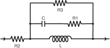
These small-signal models capture frequency-dependent inductance and resistance using Laplace elements. The models are based on low-current frequency sweeps and can be used in most SPICE simulators. They are measurement-based, not basic idealized models, providing realistic results at high frequencies. The capacitance with series resistance (R1) makes these models appropriate for a preliminary EMI analysis.

Figure 2. Coilcraft Advanced Frequency-domain Model Schematic
Also for small-signal simulations, Modelithics’ MVP library of Coilcraft RF inductors captures substrate-dependent PCB parasitic effects. These measurement-based models were developed by Modelithics and are available for download from the Modelithics website.
To address the need for small-signal transient and steady state time-domain simulations of our power inductors and chokes, Coilcraft has developed measurement-based impedance models for LTspice. These are included in the Coilcraft LTspice inductor library. The impedance models use fixed value inductance, resistance and capacitance elements for time-domain simulations that avoid DC operating point errors involved with Laplace elements.
Coilcraft has also developed large-signal inductor saturation models for our soft-saturating power inductors. These are included in the Coilcraft LTspice inductor library. The saturation models capture any inductance drop at higher current levels, which provides more meaningful ripple current simulations in power supplies. These models are based on inductance vs current measurements for each individual inductor.
.jpg "doc1710_Impedance_Model-(2).jpg")
Figure 3. Coilcraft Impedance Model Schematic
While a universal SPICE model that captures all loss mechanisms is not readily available, Coilcraft has developed loss calculation tools for our power inductors. The loss calculations are based on measurements under a wide range of conditions. They include DC and AC loss, comprising core loss, skin effect, and proximity effect. These loss calculations are based on user-entered operating conditions, such as switching frequency, ripple current, and ambient temperature. The calculations are built into our online Power Inductor Finder and Analyzer and DC-DC Optimizer tools.
See part II, to learn how to overcome challenges and limitations of modeling transformers in SPICE.


