Website-Einstellungen

Lager
Spracheinstellungen
Währungseinstellungen
Produkte
Informationsmaterial
Video-Bibliothek
Cx Family Common Mode Chokes
0402CT Low Profile Chip Inductors
Inductors Explained by Coilcraft & Mouser
XGL4020 Ultra-low DCR Power Inductors

Working Voltage Ratings of Transformers

Technical Note
A transformer does not have one universally applicable working voltage rating. Its suitability depends on the transformer insulation system, the voltages and transients in the circuit, the required type of insulation, the operating environment, and the governing safety standard.

Introduction

Voltage ratings are routinely published for many electronic components, but a single working voltage rating is often not published for power conversion transformers. The reason is that safe working voltage is not determined by the transformer alone. It depends on the insulation construction and on how and where the transformer is used. 

This note explains the principal transformer and application factors needed to determine whether a transformer insulation system is suitable for a particular application.

Working Voltage

Working voltage is the highest RMS voltage, or DC  voltage, that can occur continuously across an insulation barrier under normal operating conditions. Depending on the governing standard, the evaluation may include no-load or open-circuit conditions and recurring peak voltage in addition to RMS or DC stress.

Working voltage is primarily an insulation-coordination and safety parameter. It should not be confused with dielectric withstand voltage, impulse voltage, or  short-duration transient voltage. These parameters address different electrical stresses and are evaluated separately under the applicable standard.

Why One Rating Is Usually Not Enough

A transformer manufacturer controls the physical insulation system, including materials, winding construction, spacings, and manufacturing processes. The equipment designer controls or specifies the circuit voltages, required protection level, installation environment, altitude, and applicable safety standard. Because both sets of information are needed, a transformer cannot generally be assigned one working-voltage value that is valid for every application. (See Figure 1)
 
Transformer Design & Material Factors Application-related factors
Dielectric-withstand capability Required working voltage and recurring 
peak voltage
Insulation materials and material group Required insulation type: functional, basic, 
supplementary, double, or reinforced
Creepage and clearance provided Overvoltage category and required impulse withstand
Solid-insulation construction Pollution degree and expected contamination 
or condensation
Winding and terminal geometry Operating altitude and governing safety standard

Figure 1. Transformer vs Application-related factors 


Dielectric-withstand and partial-discharge testing

A dielectric-withstand, or hipot, test applies a specified voltage across an insulation barrier for a specified time. The test verifies that the insulation withstands the required electrical stress without breakdown or excessive leakage current. For a transformer, the test may be applied between windings and between windings and accessible conductive parts or the core, as applicable.

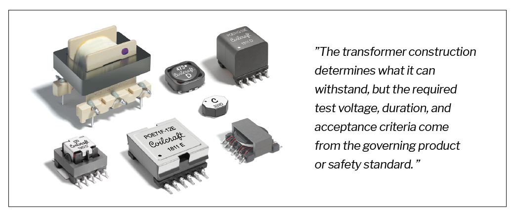
The transformer construction determines what it can withstand, but the required test voltage, duration, and acceptance criteria come from the governing product or safety standard. A successful hipot test therefore demonstrates compliance with a specified test condition; it does not, by itself, establish a universal continuous working-voltage rating.

Partial-discharge testing detects localized discharges within or along insulation before complete breakdown occurs. It can reveal defects or high-field regions that may not cause immediate failure during a conventional withstand test. Where required by the applicable standard and voltage stress, partial-discharge performance is an additional consideration, not a substitute for dielectric-withstand testing. Because partial discharge testing detects voltage-related effects below the hipot test level, it is useful when establishing a long term continuous voltage rating.

Insulating-material group

Material group classifies an insulating material according to its resistance to surface tracking. The classification is based on the material's Comparative Tracking Index (CTI), typically determined using IEC 60112. A higher CTI indicates better resistance to tracking. Material group primarily affects required creepage distance. It generally does not determine clearance through air. (See Figure 2)

Material Group Comparative 
Tracking Index (CTI)
I CTI = 600 V
II 400 V = CTI < 600 V
IIIa 175 V = CTI < 400 V
IIIb 100 V = CTI < 175 V

Figure 2. Material Group and CTI

Clearance and creepage

Clearance is the shortest distance through air between two conductive parts. Required clearance is driven mainly by the applicable impulse withstand voltage, the electric-field conditions, altitude, and the governing standard.

Creepage is the shortest distance along the surface of solid insulation between two conductive parts. Required creepage is driven mainly by working voltage, pollution degree, material group, insulation type, and the governing standard.

Summary:
•    Impulse withstand requirement + altitude + field conditions —> major inputs to clearance
•    Working voltage + pollution degree + material group + insulation type —> major inputs to creepage

The transformer manufacturer chooses the spacings when selecting a bobbin for the component. The equipment designer must compare those spacings with the requirements that apply in the end application.

doc1950-transformer-photo.png

Application Factors

Insulation type

Insulation type describes the protection provided by an insulation barrier. The term “insulation class” should be avoided here because it can be confused with thermal insulation class.

The declared insulation type cannot be established from dielectric strength alone. The complete insulation system must satisfy the construction, spacing, test, and qualification requirements of the governing standard. There is no single creepage or clearance value associated with each insulation type; the required values depend on the full set of application conditions. (See Figure 3)
 
Designation Meaning Safety Significance
Functional Insulation needed for correct operation. Not relied upon by itself for protection against electric shock. Applicable standards may still impose spacing or insulation requirements for functional reliability, fire prevention, or other hazards.
Basic Insulation applied to hazardous live parts. Provides one level of protection against electric shock.
Supplementary Independent insulation provided in addition to basic insulation. Provides protection if the basic insulation fails.
Double Basic insulation plus 
supplementary insulation.
Provides two independent levels of insulation 
protection.
Reinforced A single insulation system equivalent to double insulation. Provides protection equivalent to basic plus supplementary insulation; it does not  necessarily consist of two physically separate layers

Figure 3. Insulation Type and Safety Significance

Overvoltage category

Overvoltage category (OVC) describes the transient overvoltage environment at a location within an electrical installation. It helps establish the required impulse withstand voltage and therefore strongly influences clearance.

Working voltage describes continuous electrical stress, whereas overvoltage category describes the expected transient environment. Both must be considered. (See Figure 4)
 
Category Typical location General description
OVC I Protected electronic circuits Transient overvoltages are limited to a low level by protective measures.
OVC II Plug-connected equipment and appliances Equipment supplied from ordinary building branch circuits.
OVC III Fixed installation and distribution Distribution equipment, circuit breakers, and permanently connected industrial equipment.
OVC IV Origin of the installation Service entrance, meters, and primary overcurrent-protection equipment.

Figure 4. Overvoltage Categories and Circuit Locations

Pollution degree

Pollution degree classifies the expected contamination in the microenvironment around insulation. Pollution can reduce surface resistance, especially when moisture or condensation is present, and therefore has a direct effect on required creepage distance.

A higher pollution degree generally requires greater creepage distance. Better tracking resistance, represented by a higher CTI and a better material group, may reduce the required creepage distance where permitted by the governing standard. Condensation and ionic contamination, such as flux residue, salts, or dust, can substantially increase tracking risk and should be considered when assigning the pollution degree or selecting protective measures. (See Figure 5)
 
Degree Typical environment General description
PD1 Sealed or specially protected electronics No pollution, or only dry nonconductive pollution having 
no influence.
PD2 Homes, offices, laboratories, protected equipment Normally nonconductive pollution; temporary conductivity caused by condensation may occur.
PD3> Industrial areas or equipment exposed to dust or moisture Conductive pollution occurs, or dry pollution becomes 
conductive because of expected condensation.
PD4 Outdoor or severe exposure Persistent conductivity caused by conductive dust, rain, snow, or similar conditions.

Figure 5. Pollution Degree and Typical Environments

Altitude

At higher altitude, lower air pressure reduces dielectric strength for many practical clearance distances. Safety standards account for this effect by requiring increased clearance, or an altitude correction factor, above a specified reference altitude, commonly 2,000 m.

Paschen's law describes gas breakdown as a function of pressure and gap distance. Although the underlying relationship is nonlinear, equipment standards normally address altitude through prescribed clearance  corrections rather than by requiring designers to calculate a Paschen curve. Very low-pressure and aerospace applications require separate evaluation because equipment may pass through pressure-distance conditions that increase the risk of corona or arcing.

Working voltage requirement and governing standard

The equipment designer must determine the voltage stress across the specific insulation barrier under normal operation, including relevant no-load and open-circuit conditions. The applicable product standard then defines how that voltage, recurring peak voltage, impulse withstand voltage, insulation type, pollution degree, material group, and altitude are used to determine required insulation construction and spacings.

When the end application is unknown, a transformer manufacturer generally cannot claim universal suitability. Instead, the manufacturer can provide component construction data and evaluate suitability when the application conditions and governing standard are known.

Information Needed for a Suitability Review

At minimum, provide the following information when asking a transformer manufacturer to evaluate an application:
  • Maximum working voltage across each relevant insulation barrier
  • Maximum recurring peak voltage and waveform, when required by the standard
  • Required insulation type
  • Overvoltage category or required impulse withstand voltage
  • Pollution degree
  • Maximum operating altitude
  •  Applicable equipment or safety standard
  • Any special environmental conditions, such as condensation, coating, potting, or low pressure
The manufacturer can then compare these requirements with the transformer’s dielectric withstand capability, insulation materials, solid-insulation construction, and available creepage and clearance.

Working-Voltage Example

When developing new power transformers, Coilcraft typically applies the safety calculations of IEC 61558-1:2017 Tables 14, 20 & 21 when provided sufficient information regarding the application conditions and safety requirements. Our altitude corrections reference IEC 60664-1:2007 Table A.2.

The following examples (See Figure 6) illustrate how the same transformer can have different allowable working voltages depending on the required insulation type. The values shown apply only to the stated conditions and design basis.
 
Condition Reinforced-insulation example Basic-insulation example
ZG3651-AE and ZG3652-AE 130 V working voltage 450 V working voltage
ZG3653-AE and ZG3654-AE 275 V working voltage 550 V working voltage
Altitude 2,000 m 2,000 m
Overvoltage category II II
Pollution degree 2 2
Design basis IEC 61558-1 IEC 61558-1

Figure 6. Example of How Insulation Type Requirements Change Working Voltage Limits


Creepage and clearance between primary and secondary windings are 4.9 mm for ZG3651-AE and ZG3652-AE, and 5.9 mm for ZG3653-AE and ZG3654-AE.

Contact [email protected] to confirm suitability under other application conditions.

Conclusion

Transformer working voltage is an application-dependent result, not simply an intrinsic component rating. Transformer materials and construction establish the insulation capability available, while the circuit, required insulation type, transient environment, pollution degree, altitude, and governing standard establish what is required.

Accordingly, the most useful question is not simply, “What is the working-voltage rating of this transformer?” Instead, provide the application conditions and ask, “Is this transformer insulation system suitable for this application?”
Doc1950

Questions or Concerns?

Ask View FAQs


General Applications

Handling and Processing

RF Inductors

Power Conversion

EMI/RFI Filtering

Special Applications