サイトの設定

倉庫
言語の設定
通貨の設定
製品
リソース
ビデオライブラリ
Cx Family Common Mode Chokes
0402CT Low Profile Chip Inductors
XAL7050 High-inductance Shielded Power Inductors
XGL4020 Ultra-low DCR Power Inductors

MSD1583 Series

Shielded Coupled Power Inductors

RoHS準拠 ハロゲンフリー
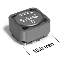
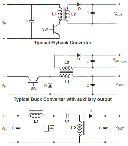
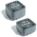
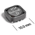
Coilcraft's MSD1583 Series of 1:1 coupled power inductors feature magnetic shielding for compact packaging and tight winding-to-winding coupling. They are ideal for Flyback, SEPIC, Ćuk, Zeta and other applications.
  • Ideal for Flyback, SEPIC, Ćuk, Zeta and other applications
  • Magnetic shielding allows high-density mounting
  • Tight winding coupling
  • Industry standard footprint
See Selecting inductors for SEPIC

今すぐ購入:
個数 単価
1 $3.95
300 $2.59
600 $1.56
1200 $1.21
2400 $1.04
4800 $0.96

大量のご注文または在庫のない商品については、お見積もりをご依頼ください

. 在庫あり、即日出荷可能.
サンプルを依頼:

デザイナーズキット:
キット 価格
C463 41 (3 of each) $160.00

仕様

Electrical specifications at 25°C.

フライバック用途

部品番号 1
(Hover for schematics)
インダクタンス (µH) 2 公差 (%) DCR (Ω) 3 絶縁
電圧 (V)
漏れ
インダクタンス (µH) 5
巻数比
typ max
MSD1583-103ME_ 10 20 0.026 0.031 500 0.33 1 : 1
MSD1583-123ME_ 12 20 0.029 0.037 500 0.36 1 : 1
MSD1583-153ME_ 15 20 0.039 0.045 500 0.38 1 : 1
MSD1583-183ME_ 18 20 0.042 0.048 500 0.40 1 : 1
MSD1583-223ME_ 22 20 0.054 0.065 500 0.40 1 : 1
MSD1583-333ME_ 33 20 0.083 0.095 500 0.54 1 : 1
MSD1583-473ME_ 47 20 0.10 0.12 500 0.46 1 : 1
MSD1583-683ME_ 68 20 0.15 0.17 500 0.79 1 : 1
MSD1583-104KE_ 100 10 0.23 0.26 500 0.59 1 : 1
MSD1583-154KE_ 150 10 0.34 0.38 500 0.70 1 : 1
MSD1583-224KE_ 220 10 0.42 0.46 500 0.89 1 : 1
MSD1583-474KE_ 470 10 0.95 1.0 500 1.2 1 : 1
MSD1583-105KE_ 1000 10 2.2 2.4 500 2.0 1 : 1

SEPIC用途

部品番号 1
(Hover for schematics)
インダクタンス (µH) 2 公差 (%) DCR (Ω) 3 SRF typ (MHz) 4 結合係数 漏れ
インダクタンス (µH) 5
Isat (A) 6 Irms (A)
typ max 10% drop 20% drop 30% drop 両方の巻線 7 単一巻線 8
MSD1583-103ME_ 10 20 0.026 0.031 16.0 0.98 0.33 11.7 13.3 14.5 3.7 5.2
MSD1583-123ME_ 12 20 0.029 0.037 14.5 0.98 0.36 10.6 12.1 13.2 3.5 5.0
MSD1583-153ME_ 15 20 0.039 0.045 12.0 0.99 0.38 9.5 10.8 11.8 3.2 4.5
MSD1583-183ME_ 18 20 0.042 0.048 11.5 0.99 0.40 8.7 9.9 10.8 3.0 4.3
MSD1583-223ME_ 22 20 0.054 0.065 10.5 0.99 0.40 7.9 9.0 9.8 2.4 3.5
MSD1583-333ME_ 33 20 0.083 0.095 8.0 0.99 0.54 6.4 7.3 8.0 2.2 3.1
MSD1583-473ME_ 47 20 0.10 0.12 7.1 0.99 0.46 5.4 6.1 6.7 2.0 2.8
MSD1583-683ME_ 68 20 0.15 0.17 5.7 0.99 0.79 4.5 5.1 5.5 1.6 2.2
MSD1583-104KE_ 100 10 0.23 0.26 5.1 >0.99 0.59 3.7 4.2 4.6 1.2 1.8
MSD1583-154KE_ 150 10 0.34 0.38 3.7 >0.99 0.70 3.0 3.4 3.8 1.1 1.5
MSD1583-224KE_ 220 10 0.42 0.46 3.2 >0.99 0.89 2.5 2.8 3.1 0.92 1.3
MSD1583-474KE_ 470 10 0.95 1.0 2.2 >0.99 1.2 1.7 1.9 2.1 0.65 0.92
MSD1583-105KE_ 1000 10 2.2 2.4 1.6 >0.99 2.0 1.2 1.3 1.5 0.42 0.60
メモ
  1. When ordering, please specify termination and packaging codes: e.g. MSD1583-105KEC
  2. Inductance shown for each winding, measured at 100 kHz, 0.1 Vrms, 0 Adc on an Agilent/HP 4284A LCR meter or equivalent.
    For SEPIC: When leads are connected in parallel, inductance is the same value. When leads are connected in series, inductance is four times the value.
  3. DCR is for each winding. DCR at 25°C. For other operating temperatures, use this DCR at Temperature calculator.
    For SEPIC: When leads are connected in parallel, DCR is half the value. When leads are connected in series, DCR is twice the value.
  4. SRF measured using an Agilent/HP 4191A or equivalent. When leads are connected in parallel, SRF is the same value.
  5. Leakage inductance is for L1 and is measured with L2 shorted.
  6. Isat: DC current, at which the inductance drops the specified amount from its value without current. It is the sum of the current flowing in both windings.
  7. Irms, both windings: Equal current when applied to each winding simultaneously that causes a 40°C temperature rise from 25°C ambient. This information is for reference only and does not represent absolute maximum ratings. Determine temperature rise.
  8. Irms, one winding: Current when applied to one winding that causes a 40°C temperature rise from 25°C ambient. This information is for reference only and does not represent absolute maximum ratings. Determine temperature rise.

終端処理:

  • E = Halogen free component. RoHS compliant matte tin over nickel over phos bronze terminations.
  • Q = RoHS tin-silver-copper (95.5/4/0.5). (Special order, added cost)
  • P = non-RoHS tin-lead (63/37). (Special order, added cost)

パッケージ:

  • D = 13″ machine-ready reel. EIA-481 embossed plastic tape (300 parts per full reel).
  • B = Less than full reel. In tape, but not machine ready. To have a leader and trailer added ($25 charge), use code letter D instead.
環境
環境:
RoHS準拠 , ハロゲンフリー
周囲温度範囲:
–40°C to +85°C with (40°C rise) Irms current
保管温度範囲:
Component: –40°C to +125°C
Tape and reel packaging: –40°C to +80°C
最大部品温度:
+125°C (ambient + temp rise)
時間内の障害(FIT)/平均障害間隔(MTBF):

性能曲線

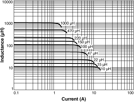
Inductance vs Current

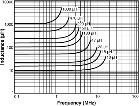
Inductance vs. Frequency

回路図

msd1583schem.gif

物理的特徴

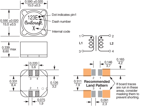
msd1583d.gif
dims_inches_mm.gif

テープ&リール仕様

tapereel_pl.gif

 
Parts per reel Reel dimensions (mm) Tape dimensions (mm) Orientation
13" (330 mm) A B C D E W P Po P1 H T part_or_ak.gif
300 330 100 13 38,4 32,4 32 24 4 2 8,6 0,5

一般仕様

コア材料:
Ferrite
重量:
3.7 – 4.4 g
パッケージ:
300/13″ reel; Plastic tape: 32 mm wide, 0.5 mm thick, 24 mm pocket spacing, 8.6 mm pocket depth.
Winding to Winding Isolation:
500 Vrms, one minute

はんだ付け/洗浄

湿度感度レベル(MSL):
1 (unlimited floor life at <30°C / 85% relative humidity)
はんだに対する耐熱性:
Max three 40 second reflows at +260°C, parts cooled to room temperature between cycles
はんだ付けする前に、 Coilcraftコンポーネントのはんだ付けを参照してください。
PCB洗浄:
Tested with pure water or alcohol only. More info.

関連製品ファミリー