사이트 설정

창고
언어 설정
통화 설정
리소스
비디오 라이브러리
Cx Family Common Mode Chokes
0402CT Low Profile Chip Inductors
XAL7050 High-inductance Shielded Power Inductors
XGL4020 Ultra-low DCR Power Inductors

Designing Common Mode Filters

Line filters prevent excessive noise from being conducted between electronic equipment and the AC line. Noise is typically common to both lines and in the same direction.

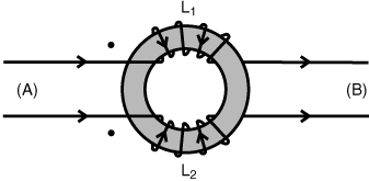
Common mode chokes are designed so that common mode current creates a magnetic flux (through mutual inductance) that adds to attenuate the CM noise signal.

The normal (differential) mode currents create magnetic flux that ideally cancel each other out so the normal signal frequencies are not attenuated.

cm_design1.gif

Any inductance encountered by the differential signal is the result of imperfect coupling of the two coils.


First order filters

First order filters use a single common mode choke and are the least expensive to design vs. higher-order filters.

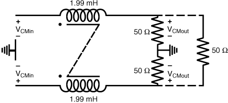
The required inductance value is just the load (in Ohms) divided by the radian frequency (2pi*f) at and above which the signal is to be attenuated, e.g. L=1.99 mH for 4 kHz cut-off into a 50 Ohm load. For a first-order filter, attenuation is 3 dB at the cut-off, increasing by 6 dB per octave at higher frequencies.

A first order common mode filter configuration would be as follows:
cm_design2.gif

Second order filters

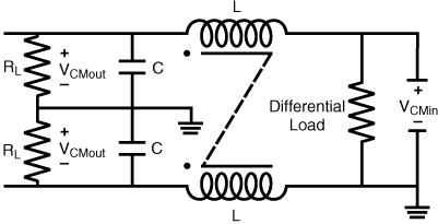
Second order filters use two reactive components (choke and cap) and have two advantages over the first order filter:

  1. They provide 12 dB per octave attenuation (four times that of a first order filter) after the cutoff point, and
  2. They provide greater attenuation at frequencies above inductor self-resonance.
    A second order common mode filter configuration would be as follows:
cm_design3.gif

See Common Mode Filter Design Guide for a detailed discussion of common mode filter designs.

See Common Mode Filter Inductor Analysis for a comprehensive discussion of common mode chokes