Site Settings

Warehouses
Language settings
Currency settings
Resources
Video Library
Cx Family Common Mode Chokes
0402CT Low Profile Chip Inductors
XAL7050 High-inductance Shielded Power Inductors
XGL4020 Ultra-low DCR Power Inductors

0603AF (1608) Series

Wirewound Ferrite Beads

RoHS compliant halogen free
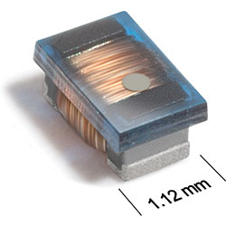
Our 0603AF Series of wirewound ferrite beads feature heavy guage wire for high current handling and are great for RF signal isolation and power supply filtering applications. This series covers a wide range of impdedance values from 9 Ohms to 3800 Ohms at 100 MHz and comes with a tight ±5% standard tolerance on all values.
  • Higher performance than other surface mount ferrite beads in the market
  • High impedance across a wide bandwidth; up to GHz band
  • Ferrite construction and heavy gauge wire for high current handling
  • Extremely low DCR for high current applications
  • Eliminates high-frequency noise in power supplies or RF signal isolation applications
Need parts for space, military or other critical applications? 
 - See Coilcraft CPS 312RAM series.

Need parts for space, military or other critical applications?
See Coilcraft AR312RAM Series | See Coilcraft ST312RAM Series
Buy Now:
Count Unit price
1 $1.27
200 $0.96
500 $0.73
1000 $0.50
2000 $0.38
4000 $0.28

For high volume or non-stock items, request a quote.

. in stock, ready to ship today.
Request a Sample:
Designer's Kit:
Kit Values Price
C439 27 (10 of each) $70.00

Specifications

Electrical specifications at 25°C.

Part number 1 Inductance (nH) 2
(Tolerance: ±5%)
Impedance typ (Ω) SRF typ (MHz) 3 DCR max (Ω) 4 Irms (A) 5 Color code 6
100 MHz 900 MHz
0603AF-15NXJR_ 15 @ 7.9 MHz 8.8 74.8 3500 0.023 2.10 Yellow
0603AF-33NXJR_ 33 @ 7.9 MHz 18.7 165 2300 0.028 1.90 Red
0603AF-39NXJR_ 39 @ 7.9 MHz 22.3 199 2200 0.115 1.00 Green
0603AF-47NXJR_ 47 @ 7.9 MHz 28.4 243 2250 0.052 1.70 White
0603AF-50NXJR_ 50 @ 7.9 MHz 30.2 268 1830 0.052 1.70 Violet
0603AF-68NXJR_ 68 @ 7.9 MHz 38.3 374 1500 0.150 0.88 Gray
0603AF-72NXJR_ 72 @ 7.9 MHz 45.6 418 1800 0.065 1.50 Blue
0603AF-85NXJR_ 85 @ 7.9 MHz 50.8 504 1600 0.065 1.50 Brown
0603AF-111XJR_ 110 @ 7.9 MHz 68.3 754 1230 0.060 1.60 Red
0603AF-121XJR_ 120 @ 7.9 MHz 70.5 861 1150 0.089 1.40 Black
0603AF-151XJR_ 151 @ 7.9 MHz 87.6 960 1050 0.093 1.50 Yellow
0603AF-201XJR_ 201 @ 7.9 MHz 117 1733 880 0.115 1.40 Green
0603AF-241XJR_ 240 @ 7.9 MHz 143 2226 900 0.120 0.85 Violet
0603AF-271XJR_ 270 @ 7.9 MHz 172 3102 750 0.220 0.68 Brown
0603AF-361XJR_ 360 @ 7.9 MHz 214 3696 700 0.210 0.65 Blue
0603AF-391XJR_ 391 @ 7.9 MHz 232 5033 700 0.300 0.64 Black
0603AF-421XJR_ 420 @ 7.9 MHz 259 5199 685 0.330 0.61 Red
0603AF-471XJR_ 470 @ 7.9 MHz 299 6332 575 0.370 0.61 Orange
0603AF-561XJR_ 560 @ 7.9 MHz 364 5135 515 0.490 0.53 Blue
0603AF-601XJR_ 601 @ 7.9 MHz 355 7687 540 0.552 0.51 Blue
0603AF-681XJR_ 680 @ 7.9 MHz 435 6312 530 0.460 0.49 Orange
0603AF-821XJR_ 820 @ 7.9 MHz 527 211 325 0.580 0.42 Green
0603AF-102XJR_ 1000 @ 7.9 MHz 666 3993 400 0.840 0.40 Black
0603AF-152XJR_ 1500 @ 7.9 MHz 940 3116 330 1.300 0.28 Orange
0603AF-222XJR_ 2200 @ 7.9 MHz 3808 64.3 85.0 1.100 0.32 Red
0603AF-472XJR_ 4700 @ 7.9 MHz 746 48.1 60.0 1.500 0.26 Yellow
0603AF-103XJR_ 10000 @ 2.5 MHz 1271 125 40.0 4.500 0.18 Gray
Notes
  1. When ordering, please specify termination and packaging codes: e.g. 0603AF-103XJRW
  2. Inductance measured at 0.1 Vrms, using a Coilcraft SMD-A fixture in an Agilent/HP 4286A impedance analyzer with Coilcraft-provided correlation pieces.
  3. SRF measured using an Agilent/HP 8753D network analyzer and a Coilcraft SMD-D test fixture.
  4. DCR measured at 25°C using a Cambridge Technology Micro-ohmmeter. For other operating temperatures, use this DCR at Temperature calculator.
  5. Irms: Current that causes a 15°C temperature rise from 25°C ambient. This information is for reference only and does not represent absolute maximum ratings. Because of their open construction, these parts will not saturate.
  6. Each part is marked with a single dot. The color dots are not unique identifiers and correspond to multiple inductance values.

Termination:

  • R = RoHS compliant. Matte Sn over Ni over Ag-Pt-glass frit terminations.
  • Q = RoHS Sn/Ag/Cu (95.5/4.0/0.5) (Special order, added cost)
  • P = Not RoHS Sn/Pb (63/37) (Special order, added cost)

Packaging:

  • W = 7” machine-ready reel. EIA-481 punched paper tape (2000 parts per full reel). Quantities less than full reel available: in tape (not machine ready) or with leader and trailer ($25 charge).
  • Y = 13″ machine-ready reel. EIA-481 punched paper tape. Factory order only, not stocked (10000 parts per full reel).
  • U = Less than full reel. In an effort to simplify our part numbering system, Coilcraft is eliminating the need for multiple packaging codes. When ordering, simply change the last letter of your part number from U to W.
Environmental
Environmental:
RoHS compliant , halogen free
Ambient temperature range:
–40°C to +85°C with Irms current
Storage temperature range:
Component: –40°C to +100°C.
Tape and reel packaging: –40°C to +80°C
Maximum part temperature:
+100°C (ambient + temp rise)
Failures in Time (FIT) / Mean Time Between Failures (MTBF):

Performance curves

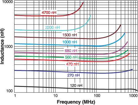
Inductance vs. Frequency

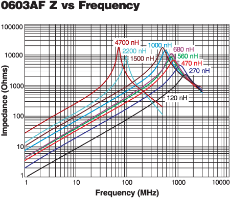
Impedance vs. Frequency

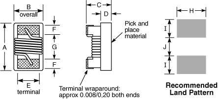
Physical characteristics

0603afd.gif
 
A max B max C max D E F G H I J
0.071 0.044 0.036 0.015 0.030 0.013 0.034 0.040 0.025 0.025 inches
1,80 1,12 0,91 0,38 0,76 0,33 0,86 1,02 0,64 0,64 mm
Height dimension (C) is before optional solder application.
For maximum height dimension including solder, add 0.006 in / 0,152 mm.

Tape and Reel specification

tapereel_pa.gif


Parts per reel Reel dimensions (mm) Tape dimensions (mm) Orientation
7" (178 mm) 13" (330 mm) A B C D E W P Po P1 T part_or_i.gif
2000 10000* 178/330 60/100 13 14,4 8,4 8 4 4 2 1,0
* Special order

General specification

Core Material:
Ferrite
Weight:
4.3 – 5.7 mg
Packaging:
2000/7″reel; 10000/13″ reel Plastic tape: 8 mm wide, 1 mm thick, 4 mm pocket spacing

Soldering/Washing

Moisture Sensitivity Level (MSL):
1 (unlimited floor life at <30°C / 85% relative humidity)
Resistance to soldering heat:
Max three 40 second reflows at +260°C, parts cooled to room temperature between cycles
Refer to Soldering Coilcraft Components before soldering.
PCB Washing:
Tested to MIL-STD-202 Method 215 plus an additional aqueous wash. More info.

Related product series