Site Settings
Products
Products
Power
RF
Transformers
Design Support Tools
Use our suite of tools to help select, analyze and compare inductors
See all tools
Parametric Search
View our list of inductors and filter results based on your exact parameters
Explore
Applications
Resources
![YouTube preview image]()
![YouTube preview image]()
![YouTube preview image]()
![YouTube preview image]()
Resources
Product Documentation
Handling & Processing
Models & Layout Tools
Video Library

Cx Family Common Mode Chokes

0402CT Low Profile Chip Inductors

XAL7050 High-inductance Shielded Power Inductors

XGL4020 Ultra-low DCR Power Inductors
Student Support
Learn more about magnetics, request free samples or ask our engineers a question.
Get Support
Quality
Quality
Quality Certification
Material Certification
Safety Certification
Handling / Processing
About
About
About
Careers
Locations



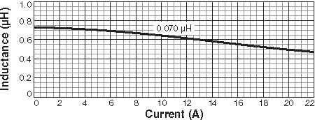
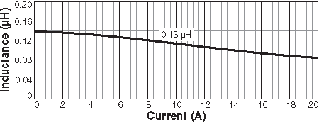
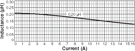
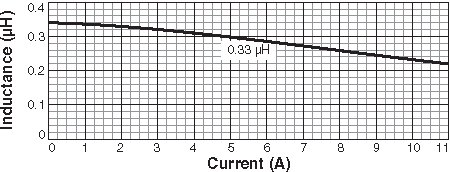
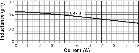
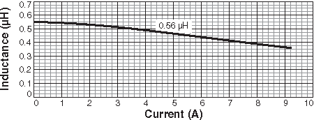
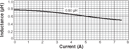
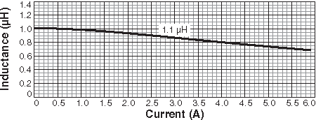
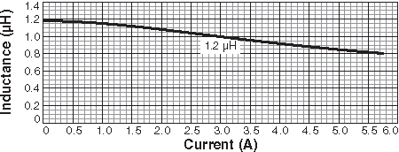
.gif)


