Site Settings

Warehouses
Language settings
Currency settings
Resources
Video Library
Cx Family Common Mode Chokes
0402CT Low Profile Chip Inductors
XAL7050 High-inductance Shielded Power Inductors
XGL4020 Ultra-low DCR Power Inductors

RFC0807B Series

Power Inductors

RoHS compliant halogen free AEC-Q flag

Great news! More choices!

See the RFC0807BV series for high operating voltage of 800 V.
See the RFB0807 series for lower values <12 µH. The RFB0807 is the same size and has the same PC board layout.

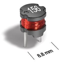
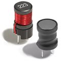
Coilcraft RFC0807B Series unshielded, radial-leaded inductors are a low-cost option for general-purpose applications. RFC0807B Series are cost-reduced higher inductance versions.
  • Open magnetic path
  • Rugged through-hole (TH) mount construction
  • High saturation current ratings
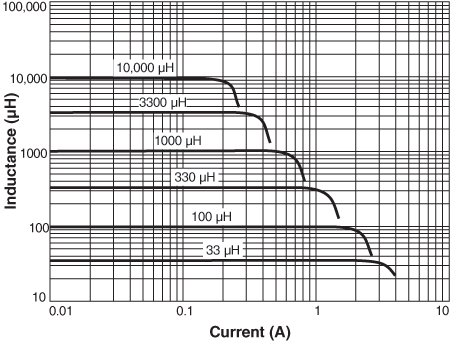
  • Ferrite core gives flat L vs I curve
  • AEC-Q200 Grade 3 (−40°C to +85°C)

Buy Now:
Count Unit price
1 $1.09
150 $0.88
300 $0.66
600 $0.40
1050 $0.31
2550 $0.27
5100 $0.25
10000 $0.23

For high volume or non-stock items, request a quote.

. in stock, ready to ship today.
Request a Sample:

Specifications

Electrical specifications at 25°C.

Part number 1 Inductance (mH) 2
(Tolerance: ±10%)
DCR (Ω) 3 SRF typ (MHz) 4 Isat (A) 5 Irms (A) 6
typ max 10% drop 20% drop 30% drop 20°C rise 40°C rise
RFC0807B-123KE 0.012 0.035 0.045 20.0 5.7 6.3 6.7 2.5 3.6
RFC0807B-153KE 0.015 0.050 0.060 19.0 5.0 5.5 5.9 2.2 3.1
RFC0807B-183KE 0.018 0.060 0.070 16.0 4.7 5.2 5.6 2.0 2.8
RFC0807B-223KE 0.022 0.075 0.090 13.0 4.1 4.6 4.9 1.8 2.5
RFC0807B-273KE 0.027 0.085 0.10 12.0 3.7 4.1 4.4 1.7 2.4
RFC0807B-333KE 0.033 0.10 0.12 12.0 3.2 3.5 3.7 1.5 2.2
RFC0807B-393KE 0.039 0.13 0.15 10.0 2.9 3.2 3.4 1.4 2.0
RFC0807B-473KE 0.047 0.15 0.17 9.2 2.6 2.9 3.0 1.3 1.8
RFC0807B-563KE 0.056 0.16 0.19 8.5 2.4 2.7 2.8 1.2 1.7
RFC0807B-683KE 0.068 0.21 0.24 7.2 2.3 2.6 2.7 1.1 1.5
RFC0807B-823KE 0.082 0.24 0.28 6.4 2.1 2.4 2.5 1.0 1.4
RFC0807B-104KE 0.100 0.31 0.36 6.1 2.0 2.2 2.3 0.85 1.3
RFC0807B-124KE 0.12 0.35 0.40 5.7 1.8 2.0 2.1 0.80 1.2
RFC0807B-154KE 0.15 0.41 0.47 5.3 1.6 1.8 1.9 0.75 1.1
RFC0807B-184KE 0.18 0.53 0.61 4.4 1.4 1.6 1.7 0.65 0.95
RFC0807B-224KE 0.22 0.60 0.69 4.1 1.3 1.5 1.6 0.60 0.85
RFC0807B-274KE 0.27 0.70 0.81 3.6 1.2 1.3 1.4 0.55 0.80
RFC0807B-334KE 0.33 0.91 1.1 3.4 1.1 1.2 1.3 0.50 0.72
RFC0807B-394KE 0.39 1.0 1.2 3.3 1.0 1.2 1.2 0.45 0.64
RFC0807B-474KE 0.47 1.4 1.6 2.9 0.90 1.0 1.1 0.40 0.55
RFC0807B-564KE 0.56 1.5 1.7 2.7 0.85 0.93 1.0 0.37 0.52
RFC0807B-684KE 0.68 1.8 2.0 2.5 0.77 0.83 0.92 0.34 0.48
RFC0807B-824KE 0.82 2.3 2.6 2.1 0.68 0.77 0.82 0.30 0.42
RFC0807B-105KE 1.0 2.6 3.0 2.0 0.62 0.68 0.72 0.28 0.40
RFC0807B-125KE 1.2 3.4 3.9 1.7 0.56 0.62 0.66 0.25 0.35
RFC0807B-155KE 1.5 4.0 4.6 1.6 0.52 0.57 0.60 0.22 0.32
RFC0807B-185KE 1.8 4.4 5.1 1.5 0.48 0.53 0.56 0.21 0.30
RFC0807B-225KE 2.2 6.0 6.9 1.3 0.43 0.47 0.49 0.18 0.26
RFC0807B-275KE 2.7 7.0 8.0 1.2 0.38 0.42 0.44 0.17 0.24
RFC0807B-335KE 3.3 9.1 10.5 1.0 0.35 0.38 0.40 0.15 0.21
RFC0807B-395KE 3.9 10.0 11.5 1.0 0.33 0.35 0.37 0.14 0.20
RFC0807B-475KE 4.7 14.0 16.0 0.90 0.29 0.31 0.33 0.12 0.17
RFC0807B-565KE 5.6 15.5 17.5 0.80 0.27 0.29 0.31 0.11 0.16
RFC0807B-685KE 6.8 20.0 23.0 0.70 0.24 0.26 0.27 0.10 0.14
RFC0807B-825KE 8.2 22.5 25.5 0.60 0.22 0.24 0.26 0.095 0.13
RFC0807B-106KE 10 25.5 28.0 0.60 0.21 0.22 0.24 0.090 0.13
RFC0807B-126KE 12 34.0 37.5 0.60 0.19 0.20 0.22 0.080 0.11
RFC0807B-156KE 15 41.5 45.5 0.50 0.16 0.18 0.20 0.070 0.10
RFC0807B-186KE 18 46.5 51.0 0.40 0.15 0.17 0.18 0.065 0.090
Notes
  1. When ordering, please specify lead length and termination codes: e.g. RFC0807B-183KE
  2. Inductance tested at 100 kHz, 0.1 Vrms, 0 Adc; measured on an Agilent/HP 4284A LCR meter or equivalent.
  3. DCR at 25°C. For other operating temperatures, use this DCR at Temperature calculator.
  4. SRF measured using an Agilent/HP 4191A or equivalent. Details
  5. Isat: DC current at 25°C that causes the specified inductance drop from its value without current. Temperature derating curves.
  6. Irms: Current that causes the specified temperature rise from 25°C ambient. This information is for reference only and does not represent absolute maximum ratings. Temperature derating curves.


Lead Length:

  • A = 3.6 mm ±0.3 mm (special order)
  • B = 5.0 mm ±0.5 mm
  • C = 7.0 mm ±0.5 mm (special order)
  • D = 8.0 mm ±0.5 mm (special order)
  • E = 10.0 mm ±1.0 mm (special order)
  • F = 25.0 mm ±1.0 mm, packaged in fanfold tape, 800 parts per box (special order)

Termination:

  • E = RoHS compliant tin-silver over tin over copper over steel.
  • S = non-RoHS tin-lead (63/37). (Special order, added cost)
Environmental
Environmental:
RoHS compliant , halogen free
Ambient temperature range:
–40°C to +85°C with (40°C rise) Irms current
Storage temperature range:
Component: –40°C to +125°C.
Tray or tape packaging: –40°C to +80°C
Maximum part temperature:
+125°C (ambient + temp rise).
Failures in Time (FIT) / Mean Time Between Failures (MTBF):

Performance curves

Inductance vs. Current

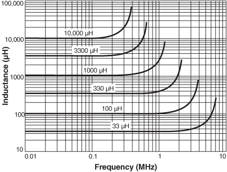
Inductance vs. Frequency

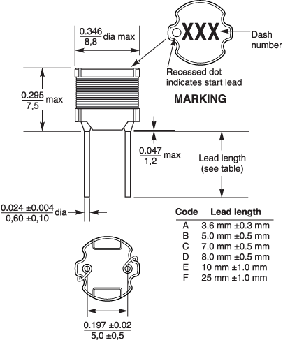
Physical characteristics

rfc0807d.gif

dims_inches_mm.gif

General specification

Core Material:
Ferrite
Weight:
1.30 – 1.50 g
Packaging:
150 parts per tray (all except 25 mm lead length). In fanfold tape, 800 parts per box (25 mm lead length only).

Soldering/Washing

Moisture Sensitivity Level (MSL):
1 (unlimited floor life at <30°C / 85% relative humidity)
Resistance to soldering heat:
Three reflows at >217°C for 90 seconds (+260°C ±5°C for 20 – 40 seconds), allowing parts to cool to room temperature between
Refer to Soldering Coilcraft Components before soldering.
PCB Washing:
Tested to MIL-STD-202 Method 215 plus an additional aqueous wash. More info.

Related product series

Related product families