|
|||
|
Power Magnetics Tools
RF Inductor Tools
CM Choke \ Ferrite Beads
LC Filter Designer IC / Inductor Match Tool Application Notes Other Resources
Designer's Kits
|
|
Part number1 Click to get parts |
![]() |
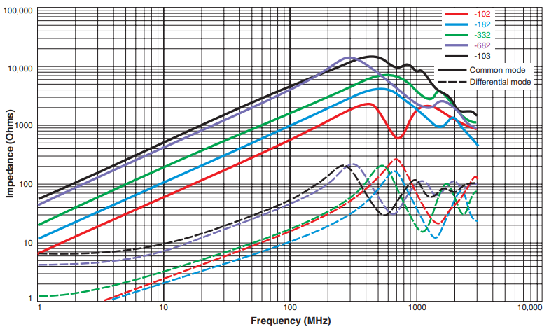
Common mode peak impedance (kOhms) |
Cutoff frequency2 (MHz) |
Inductance (µH)3 | DCR max4 (Ohms) |
Isolation5 (Vrms) |
Irms6 (A) |
|
---|---|---|---|---|---|---|---|---|
min | nom | |||||||
PFD2015-102ME_ | 2.30 @ 400 MHz | 550 | 0.80 | 1.0 | 0.165 | 250 | 0.800 | |
PFD2015-122ME_ | 3.03 @ 350 MHz | 560 | 0.96 | 1.2 | 0.175 | 250 | 0.750 | |
PFD2015-182ME_ | 4.21 @ 510 MHz | 350 | 1.44 | 1.8 | 0.294 | 250 | 0.490 | |
PFD2015-272ME_ | 6.16 @ 660 MHz | 380 | 2.16 | 2.7 | 0.477 | 250 | 0.410 | |
PFD2015-332ME_ | 7.14 @ 610 MHz | 330 | 2.64 | 3.3 | 0.670 | 250 | 0.370 | |
PFD2015-472ME_ | 9.78 @ 460 MHz | 230 | 3.76 | 4.7 | 1.00 | 250 | 0.260 | |
PFD2015-682ME_ | 14.18 @ 290 MHz | 260 | 5.44 | 6.8 | 1.75 | 250 | 0.187 | |
PFD2015-822ME_ | 13.81 @ 250 MHz | 170 | 6.56 | 8.2 | 2.50 | 250 | 0.150 | |
PFD2015-103ME_ | 14.73 @ 470 MHz | 220 | 8.00 | 10 | 3.40 | 250 | 0.130 |
1 | When ordering, please specify packaging code: e.g. PFD2015-103MEC | |
Termination: | E = RoHS compliant silver-palladium-platinum-glass frit. Special order, added cost: R = RoHS compliant matte tin over nickel over silver-platinum-glass frit. |
|
Packaging:
|
C = 7"
machine-ready reel EIA-481 embossed plastic tape 2000 parts per full reel). B = Less than full reel In tape, but not machine-ready. To have a leader and trailer added ($25 charge), use code letter C instead. D = 13" machine-ready reel EIA-481 embossed plastic tape. Factory order only, not stocked (7500 parts per full reel). |
2 | Frequency at which the differential mode attenuation equals 3 dB | |
3 | Inductance shown for each winding, measured at 100 kHz, 0.1 Vrms, 0 Adc on an Agilent/HP 4284A LCR meter or equivalent. | |
4 | DCR is for each winding, measured at 25°C. For other operating temperatures, use this DCR at Temperature calculator. | |
5 | Interwinding isolation (hipot) tested for one minute. | |
6 | Irms: Current that causes a 40°C temperature rise from 25°C ambient. This information is for reference only and does not represent absolute maximum ratings. | |
7 | Ambient temperature range: | −40°C to +85°C with Irms current. |
8 | Storage temperature range: | Component: −40°C to +125°C Tape and reel packaging: −40°C to +80°C |
9 | Maximum part temperature: | +125°C (Ambient + temperature rise) |
10 | Resistance to soldering heat: Three reflows at >217°C for 90 seconds (+260°C ±5°C for 20 – 40 seconds), allowing parts to cool to room temperature between. | |
11 | Electrical specifications at 25°C. | |
Refer to Soldering Coilcraft Components before soldering. | ||
PCB washing: Tested to MIL-STD-202 Method 215 plus an additional aqueous wash. More info. | ||
![]() |
Home | Design Tools | Samples | Kits | Price + Stock | Sales | Support | Jobs | Index | |
Your comments and suggestions are welcome. Contact [email protected] Copyright © 2019, Coilcraft, Inc. Privacy policy Updated: June 04, 2018 |
![]() ![]() ![]() |