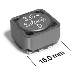
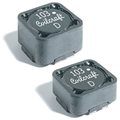
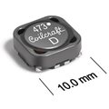
Shielded Coupled Power Inductors
MSD1583 Series
Pricing
PDF data sheet
SPECIFICATIONS
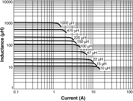
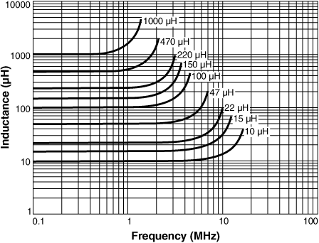
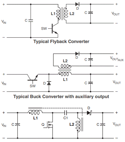
L vs Frequency L vs Current Core loss Schematics
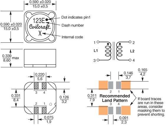
Dimensions
Tape and reel specifications
3D model
1 |
When
ordering, please specify termination and packaging codes: e.g. MSD1583-105KEC |
|
Termination: |
E = Halogen free component. RoHS compliant matte tin over nickel over phos bronze terminations.
Special order, added cost: Q = RoHS tin-silver-copper (95.5/4/0.5) or
P = non-RoHS tin-lead (63/37). |
|
Packaging:
|
D = 13"
machine-ready reel
EIA-481 embossed plastic tape 300 parts per full reel).
B = Less than full reel
In tape, but not machine-ready. To have a leader and trailer added ($25 charge),
use code letter D instead. |
2 |
Inductance shown for each winding, measured at 100 kHz, 0.1 Vrms, 0 Adc on an Agilent/HP 4284A LCR
meter or equivalent. |
3 |
Peak primary current drawn at minimum input voltage. |
4 |
DCR is for each winding. DCR at 25°C. For other operating temperatures, use this calculator. |
5 |
Leakage inductance is for L1 and is measured with L2 shorted. |
6 |
Ambient temperature range: |
−40°C to +85°C with Irms current. |
7 |
Storage temperature range: |
Component: −40°C to +125°C
Tape and reel packaging: −40°C to +80°C |
8 |
Maximum part temperature: +125°C (Ambient + temperature rise) |
9 |
Resistance to soldering heat: Three reflows at >217°C for 90 seconds (+260°C ±5°C for 20 – 40 seconds), allowing parts to cool to room temperature between. |
10 |
Electrical specifications at 25°C. |
Refer to Soldering Coilcraft Components before soldering. |
PCB washing: Tested to MIL-STD-202 Method 215 plus an additional aqueous wash. More info. |
 |
 |
1 |
When
ordering, please specify termination and packaging codes: e.g. MSD1583-105KEC |
|
Termination: |
E = Matte tin over nickel over phos bronze
Special order, added cost: Q = RoHS tin-silver-copper (95.5/4/0.5) or
P = non-RoHS tin-lead (63/37). |
|
Packaging:
|
D = 13"
machine-ready reel
EIA-481 embossed plastic tape 300 parts per full reel).
B = Less than full reel
In tape, but not machine-ready. To have a leader and trailer added ($25 charge),
use code letter D instead. |
2 |
Inductance shown for each winding, measured at 100 kHz, 0.1 Vrms, 0 Adc on an Agilent/HP 4284A LCR meter or equivalent. When leads are connected in parallel, inductance is the
same value. When leads are connected in series, inductance is four times the value. |
3 |
DCR is for each winding. When leads are connected in parallel, DCR is half the value. When leads are connected in series, DCR is twice the value.
DCR at 25°C. For other operating temperatures, use this calculator. |
4 |
SRF measured using an Agilent/HP 4191A or equivalent. When leads are connected in parallel, SRF is the same value. |
5 |
Leakage Inductance is for L1 and is measured with L2 shorted. |
6 |
Isat:
DC current, at which the inductance drops the specified amount from its value without current. It is the sum of the current flowing in both windings. |
7 |
Irms, both windings: Equal current when applied to each winding simultaneously that causes a 40°C temperature rise from 25°C ambient. This information is for reference only and does not represent absolute maximum ratings.
Determine temperature rise. |
8 |
Irms, one winding:
Current when applied to one winding that causes a 40°C temperature rise from 25°C ambient. This information is for reference only and does not represent absolute maximum ratings.
Determine temperature rise. |
9 |
Ambient temperature range: |
−40°C to +85°C with Irms current. |
10 |
Storage temperature range: |
Component: −40°C to +125°C
Tape and reel packaging: −40°C to +80°C |
11 |
Maximum part temperature: +125°C (Ambient + temperature rise) |
12 |
Resistance to soldering heat: Three reflows at >217°C for 90 seconds (+260°C ±5°C for 20 – 40 seconds), allowing parts to cool to room temperature between. |
13 |
Electrical specifications at 25°C. |
Refer to Soldering Coilcraft Components before soldering. |
 |
|
|