Site Settings

Warehouses
Language settings
Currency settings
Resources
Video Library
Cx Family Common Mode Chokes
0402CT Low Profile Chip Inductors
XAL7050 High-inductance Shielded Power Inductors
XGL4020 Ultra-low DCR Power Inductors

A Guide to Coupled Inductors

What is a coupled inductor?

A coupled inductor has two or more windings on a common core. Coupled inductors function in dc-dc converters by transferring energy from one winding to the other through the common core. They are available in many sizes, inductance values, and current ratings and most are magnetically shielded for low electromagnetic interference (EMI). The windings may have equal (1:1) or unequal turns ratios (1:N). Due to widespread demand in a variety of circuits, many 1:1 and 1:N standard coupled inductors are readily available off-the-shelf.

What are common applications for coupled inductors?

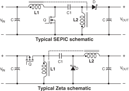
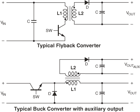
Coupled_Figure-A.gif
Typical circuits using 1:N COUPLED INDUCTORS
Figure 1

Purpose-designed coupled inductors are used in a variety of power conversion circuits such as flyback, SEPIC, Fly-Buck™, Cuk, ZETA and multi-phase topologies. These voltage regulation circuits use coupled inductors to efficiently provide the required output voltages, which may be stepped up or down from the input. To do this, SEPIC and Zeta circuits use 1:1 coupled inductors, whereas flyback and other circuits use 1:N inductors. In multi-phase power converters, coupled inductors provide inherent ripple current cancelling that is not provided by single inductors.

Coupled_Figure-B.gif
Typical circuits using 1:1 COUPLED INDUCTORS
Figure 2

You can connect coupled inductor windings in different configurations to serve different purposes. The windings may be connected to circuits separately for use as isolation transformers or as common mode chokes. You may also connect them in series to achieve a higher inductance or for use as a tapped inductor. As the use of standard coupled inductors has grown, Coilcraft datasheets now provide application-specific characterizations to help designers select the best-suited inductor.

What is the difference between a coupled inductor and a transformer?

There is often little or no physical difference between what one engineer calls a coupled inductor and another calls a transformer. Both may have either a 1:1 or 1:N turns ratio and have similar winding-core arrangements, and they may even "look the same." Actually, the most appropriate name depends on the intended application.

Coupled inductors and flyback transformers both use cores to store energy received from a winding and then transfer that energy to the other winding. For both transformers and coupled inductors, the efficacy of the winding coupling, expressed as coupling coefficient k, depends on the core material properties as well as the physical arrangement of the windings and core.

Common to transformers and coupled inductors is the fact that close coupling between the windings (k > 0.9) results in low leakage inductance and generally provides the most efficient energy transfer and widest usable frequency bandwidth. High-performance designs like Coilcraft's LPD and LPD-V families are able to provide the desired coupling factor while also providing a high measure of voltage isolation between windings.

Close coupling may not be optimal for all applications. In fact, Coilcraft's MSC1278 Series of coupled inductors is designed with high leakage inductance for use in certain SEPIC applications. The loosely coupled windings (K ≈ 0.8) improve SEPIC efficiency by reducing circulating current and still provide twice the ripple current reduction of separate inductors.

You can connect coupled inductor windings in different configurations to serve different purposes. The windings may be connected to circuits separately for use as isolation transformers or as common mode chokes. You may also connect them in series to achieve a higher inductance or for use as a tapped inductor. As the use of standard coupled inductors has grown, Coilcraft datasheets now provide application-specific characterizations to help designers select the best-suited inductor.

How do I choose a coupled inductor?

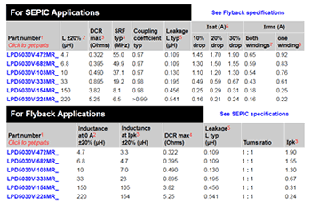
Coupled_C.gif
Application-specific data for off-the-shelf coupled inductors
Figure 3

Selection of a coupled inductor is application-dependent. As shown in Figure 3, Coilcraft datasheets characterize coupled inductors for multiple circuit uses, and Coilcraft has developed online tools for selecting coupled inductors.

For a particular inductance and current rating, our Coupled Inductor Finder Tool provides a list of off-the-shelf coupled inductors that meet those requirements.

This document describes the particular SEPIC calculations for determining the required coupled inductance parameters.

Once the values are determined for your SEPIC application, enter those values into the Coupled Inductor Finder tool to find and compare coupled inductors that meet your requirements.


What types of coupled inductors does Coilcraft manufacture?

Coilcraft designs and manufactures a variety of surface mount coupled inductors for many applications including, 1:1 low profile, low DCR, miniature, high temperature, and high isolation alternatives. Coilcraft also offers various 1:N coupled inductor alternatives in ratios from 1:1.5 up to 1:100.

Related Application Notes


Designer Kit's

What's Next?

View more: Getting Started Series