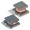
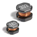
DO3316H Series High Current
Surface Mount Power Inductors
- Very high current ratings - up to 17 Arms; 28 Asat
- Low profile and small footprint - only 0.51" x
0.37" x
0.25" high
- Exceptionally low DC resistance thanks to the use of heavier
gauge wire
- Flat top and self-leaded design for reliable
surface mounting
- Robust temperature deflection prevents damage during solder
reflow
- AEC-Q200 Grade 3 (−40°C to +85°C)
- RoHS-compliant. 260°C compatible. Tin-silver-copper over copper terminations.
- COTS Plus tin-silver-copper and tin-lead terminations available
- Custom versions available
- Samples of all values are available in
Coilcraft Designer's Kit C326
- Need parts for space, military or other critical applications?
See Coilcraft CPS 563PKA series.
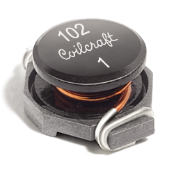
Photo
Pricing
PDF data sheet
SPECIFICATIONS
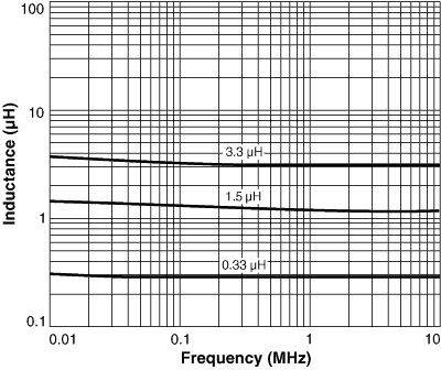
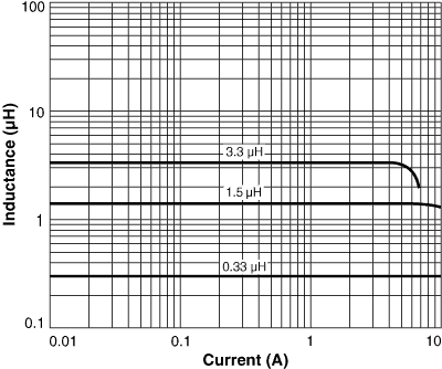
L vs Frequency L vs Current Core loss SPICE models
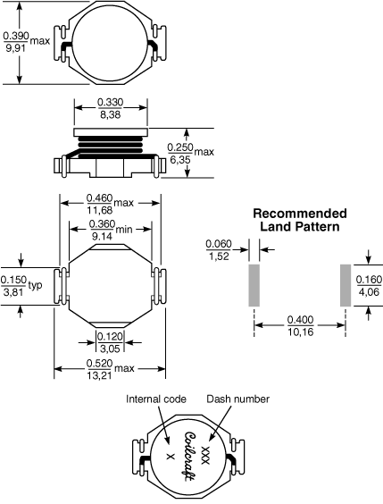
Dimensions
Tape and reel specifications 3D model
1 |
When ordering, please
specify tolerance, termination and packaging codes: e.g. DO3316H-472MLD |
|
Tolerance: |
M = 20%, K = 10% (Table above shows stock tolerances in
bold.) |
|
Termination: |
L
= RoHS compliant tin-silver (96.5/3.5) over copper.
Special order, added cost: T
= RoHS tin-silver-copper (95.5/4/0.5) over copper or
S
= non-RoHS tin-lead (63/37) over copper. |
|
Packaging: |
D = 13" reel, machine-ready
EIA-481 embossed plastic tape (750 parts per full reel).
B = Less than full reel
In tape, not machine ready. To have a leader and trailer
added ($25 charge), use code letter D instead. |
2 |
Inductance tested at 100
kHz, 0.1 Vrms using an Agilent/HP 4263B LCR meter or equivalent. |
3 |
Tolerances in bold are stocked for immediate
shipment. |
4 |
DCR measured at 25°C on a micro-ohmmeter. For other operating temperatures, use this calculator. |
5 |
SRF measured using an Agilent/HP 8753D network analyzer.
Details |
6 |
Isat: DC current at 25°C that causes a 10% (typ) inductance drop from its value without current.
Temperature derating curves. |
7 |
Irms: Current that causes a 40°C temperature rise from 25°C ambient. This information is for reference only and does not represent absolute maximum ratings. Temperature derating curves.
|
8 |
Ambient temperature range: |
−40°C to +85°C with Irms current. |
9 |
Storage temperature range: |
Component: −40°C to +125°C
Tape and reel packaging: −40°C to +80°C |
10 |
Maximum part temperature: +125°C (Ambient + temperature rise) |
11 |
Resistance to soldering heat: Three reflows at >217°C for 90 seconds (+260°C ±5°C for 20 – 40 seconds), allowing parts to cool to room temperature between. |
12 |
Electrical specifications at 25°C. |
Refer to Soldering Coilcraft Components before soldering. |
PCB washing: Tested to MIL-STD-202 Method 215 plus an additional aqueous wash.
More info. |
 |
|
|