|
|||
|
Power Magnetics Tools
RF Inductor Tools
CM Choke \ Ferrite Beads
LC Filter Designer IC / Inductor Match Tool Application Notes Other Resources
Designer's Kits
|
|
For new designs, consider the 0805HT as an alternative to this series. The 0805HT series offers more inductance values, higher SRF and better current handling. We will continue to support the 0805HS indefinitely. |
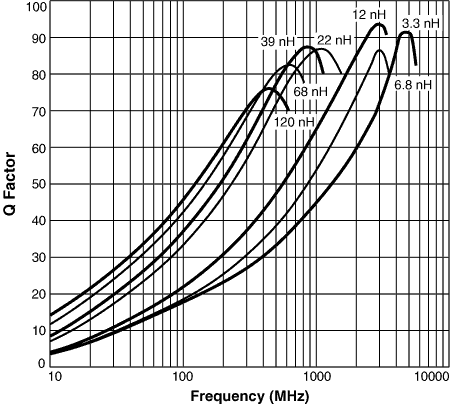
Q vs
Frequency
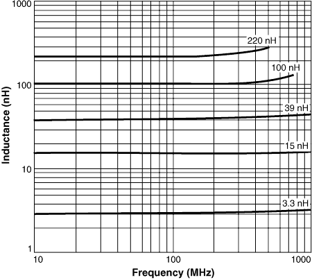
L vs Frequency
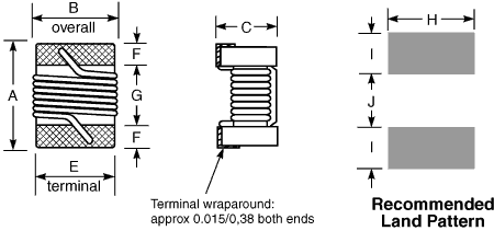
Dimensions
Tape and reel specifications
S-Parameters
SPICE models
3D model
Part number1 |
Inductance2 (nH) |
Percent tolerance3 |
Q min4 | SRF min5 (MHz) |
DCR max6 (Ohms) |
Irms7 (mA) |
Color code8 |
---|---|---|---|---|---|---|---|
0805HS-030TJL_ | 3.3 @ 250 MHz | 5 | 50 @ 1500 MHz | 7900 | 0.08 | 600 | Black |
0805HS-060TJL_ | 6.8 @ 250 MHz | 5 | 50 @ 1000 MHz | 5500 | 0.11 | 600 | Brown |
0805HS-080TJL_ | 8.2 @ 250 MHz | 5 | 50 @ 1000 MHz | 4700 | 0.12 | 600 | Red |
0805HS-100TJL_ | 10 @ 250 MHz | 5 | 60 @ 500 MHz | 4200 | 0.10 | 600 | Blue |
0805HS-120TJL_ | 12 @ 250 MHz | 5 | 50 @ 500 MHz | 4000 | 0.15 | 600 | Orange |
0805HS-150TJL_ | 15 @ 250 MHz | 5 | 50 @ 500 MHz | 3400 | 0.17 | 600 | Yellow |
0805HS-180TJL_ | 18 @ 250 MHz | 5 | 50 @ 500 MHz | 3300 | 0.20 | 600 | Green |
0805HS-220T_L_ | 22 @ 250 MHz | 5,2 | 55 @ 500 MHz | 2600 | 0.22 | 500 | Blue |
0805HS-270T_L_ | 27 @ 250 MHz | 5,2 | 55 @ 500 MHz | 2500 | 0.25 | 500 | Violet |
0805HS-330T_L_ | 33 @ 250 MHz | 5,2 | 60 @ 500 MHz | 2050 | 0.27 | 500 | Gray |
0805HS-390T_L_ | 39 @ 250 MHz | 5,2 | 60 @ 500 MHz | 2000 | 0.29 | 500 | White |
0805HS-470T_L_ | 47 @ 200 MHz | 5,2 | 60 @ 500 MHz | 1650 | 0.31 | 500 | Black |
0805HS-560T_L_ | 56 @ 200 MHz | 5,2,1 | 60 @ 500 MHz | 1550 | 0.34 | 500 | Brown |
0805HS-680T_L_ | 68 @ 200 MHz | 5,2,1 | 60 @ 500 MHz | 1450 | 0.38 | 500 | Red |
0805HS-820T_L_ | 82 @ 150 MHz | 5,2,1 | 65 @ 500 MHz | 1300 | 0.42 | 400 | Orange |
0805HS-101T_L_ | 100 @150 MHz | 5,2,1 | 65 @ 500 MHz | 1200 | 0.46 | 400 | Yellow |
0805HS-121T_L_ | 120 @ 150 MHz | 5,2,1 | 50 @ 250 MHz | 1100 | 0.51 | 400 | Green |
0805HS-151T_L_ | 150 @ 100 MHz | 5,2,1 | 50 @ 250 MHz | 920 | 0.56 | 400 | Blue |
0805HS-181T_L_ | 180 @ 100 MHz | 5,2,1 | 50 @ 250 MHz | 870 | 0.64 | 400 | Violet |
0805HS-221T_L_ | 220 @ 100 MHz | 5,2 | 50 @ 250 MHz | 850 | 0.70 | 400 | Gray |
1 | When ordering, please specify tolerance, termination and packaging codes: e.g. 0805HS-221XGLC |
Tolerance: | F = 1%, G = 2%, J = 5% (Table above shows stock tolerances in bold.) | |
Termination: | L = RoHS compliant silver-palladium-platinum-glass frit Special order, added cost: T = RoHS tin-silver-copper (95.5/4/0.5) or S = non-RoHS tin-lead (63/37). |
|
Packaging: | C = 7"
machine-ready reel EIA-481 embossed plastic tape (2000 parts per full reel). B = Less than full reel In tape, but but not machine-ready. To have a leader and trailer added ($25 charge), use code letter C instead. D = 13" reel, machine-ready EIA-481 embossed plastic tape. Factory order only, not stocked (7500 parts per full reel). |
2 | Inductance measured using a Coilcraft SMD-A fixture in an Agilent/HP 4286A impedance analyzer with Coilcraft-provided correlation pieces. | |
3 | Tolerances in bold are stocked for immediate shipment. | |
4 | Q measured using an Agilent/HP 4291A with an Agilent/HP 16193 test fixture. | |
5 | SRF measured using an Agilent/HP 8720D network analyzer and a Coilcraft SMD-D test fixture. Details | |
6 | DCR measured at 25°C on a Cambridge Technology Micro-ohmmeter and a Coilcraft CCF858 test fixture. For other operating temperatures, use this DCR at Temperature calculator. | |
7 | Irms: Current that causes a 15°C temperature rise from 25°C ambient. This information is for reference only and does not represent absolute maximum ratings. | |
8 | Each part is marked with a single dot. The color dots are not unique identifiers and correspond to multiple inductance values. Details. | |
9 | Ambient temperature range: | −40°C to +125°C with Irms current. |
10 | Storage temperature range: | Component: −40°C to +140°C Tape and reel packaging: −40°C to +80°C |
11 | Maximum part temperature: +140°C (Ambient + temperature rise) | |
12 | Resistance to soldering heat: Three reflows at >217°C for 90 seconds (+260°C ±5°C for 20 – 40 seconds), allowing parts to cool to room temperature between. | |
13 | Electrical specifications at 25°C. | |
14 | Temperature coefficient of inductance (TCL): +25 to +125 ppm/°C. | |
Refer to Soldering Coilcraft Components before soldering. | ||
PCB washing: Tested to MIL-STD-202 Method 215 plus an additional aqueous wash. More info. | ||
![]() |
Home | Design Tools | Samples | Kits | Price + Stock | Sales | Support | Jobs | Index | |
Your comments and suggestions are welcome. Contact [email protected] Copyright © 2019, Coilcraft, Inc. Privacy policy Updated: April 16, 2018 |
![]() ![]() ![]() |