0603HC (1608)
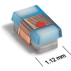
Ceramic Chip Inductors
- High current ratings – up to 2.4 Amps!
- Can handle transient currents up to 50% higher.
- Inductance values from 1.6 to 24 nH
- Higher Q factors than our 0603CS parts at low
inductance values.
- Very high self-resonant frequencies – up to 12,500 MHz
- RoHS compliant, halogen free. 260°C compatible.
Silver-palladium-platinum-glass frit terminations.
- COTS Plus tin-silver-copper and tin-lead terminations available
- Samples of all inductance values are available in Coilcraft Designer's Kit C339
Photo Pricing
PDF data sheet
SPECIFICATIONS
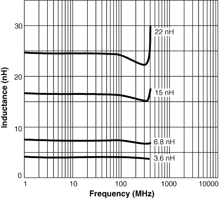
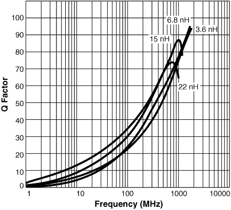
Q vs Frequency L vs Frequency 3D model
Dimensions
Tape and reel specifications S-Parameters SPICE models
1 |
When
ordering, please specify tolerance, termination and packaging codes: e.g. 0603HC-24NXGEW |
|
Tolerance: |
G = 2%, J = 5% (Table above shows stock tolerances in bold.) |
|
Termination: |
E = Halogen free component. RoHS compliant. Silver-palladium-platinum-glass frit terminations.
L = RoHS compliant, not halogen-free. Silver-palladium-platinum-glass frit.
Special order, added cost: T = RoHS tin-silver-copper (95.5/4/0.5) or
S = non-RoHS tin-lead (63/37). |
|
Packaging: |
W = 7"
machine-ready reel
EIA RS-481 punched paper tape (2000 parts per full reel).
U = Less than full reel
In tape, but not machine-ready. To have a leader and trailer added ($25
charge), use code letter W instead. |
2 |
Inductance measured
at 250 MHz using a Coilcraft SMD-A fixture in an Agilent/HP 4286
impedance analyzer with Coilcraft-provided correlation pieces. |
3 |
Tolerances in bold
are stocked for immediate shipment. |
4 |
Q measured
at 250 MHz using
an Agilent/HP 4291A with an Agilent/HP 16193 test fixture. |
5 |
SRF measured using
an Agilent/HP 8720D network analyzer and a Coilcraft SMD-D test fixture. Details |
6 |
DCR measured
at 25°C on micro-ohmmeter and Coilcraft CCF858 test fixture. For other operating temperatures, use this calculator. |
7 |
Irms: Current that causes a
20°C temperature rise from 25°C ambient. This information is for reference only and does not represent absolute maximum ratings. |
8 |
Each part is marked with a single dot. The color dots are not unique identifiers and correspond to multiple inductance values. Details. |
9 |
Ambient temperature range: |
−40°C to +125°C with Irms current. |
10 |
Storage temperature range: |
Component: −40°C to +145°C
Tape and reel packaging: −40°C to +80°C |
11 |
Maximum part temperature: +145°C (Ambient + temperature rise) |
12 |
Resistance to soldering heat: Three reflows at >217°C for 90 seconds (+260°C ±5°C for 20 – 40 seconds), allowing parts to cool to room temperature between. |
13 |
Electrical specifications at 25°C. |
14 |
Temperature coefficient of inductance (TCL): +25 to +125 ppm/°C.
|
Refer to Soldering Coilcraft Components before soldering. |
PCB washing: Tested to MIL-STD-202 Method 215 plus an additional aqueous wash.
More info. |
 |
|
|
Home
|
Design Tools
|
Samples
|
Kits
|
Price + Stock
|
Sales
|
Support
|
Jobs
|
Index
|
Site Map
Your comments and suggestions are welcome. Contact [email protected]
Copyright © 2019 Coilcraft, Inc. Privacy policy
Updated: April 16, 2018
|