Site Settings

Warehouses
Language settings
Currency settings
Resources
Video Library
Cx Family Common Mode Chokes
0402CT Low Profile Chip Inductors
XAL7050 High-inductance Shielded Power Inductors
XGL4020 Ultra-low DCR Power Inductors

How to use our models in Microwave Office

Note: Even the most current version of Microwave Office may not contain up-to-date libraries of our inductor models and S-parameters. The Coilcraft SPICE models page provides the most current and accurate versions of our models on our web site.

S-parameters

Our S-parameters are provided in a single compressed "zipped" file. The file must be "unzipped" after downloading to obtain the separate inductor value S-parameter files.

  • You can either link to or import our S-parameter data files.
  • Right click over the "Data Files" folder on the left.
  • Select either "Link To Data File." or "Import Data File."
  • Browse to the folder where the unzipped files are located and select the desired S-parameter file.

To place the data file on a schematic:

  1. Select the "Elem" tab.
  2. Click on the "Subcircuits" folder.
  3. Click on the selected data file element.
  4. Drag the element onto your schematic.

Lumped element (SPICE) models

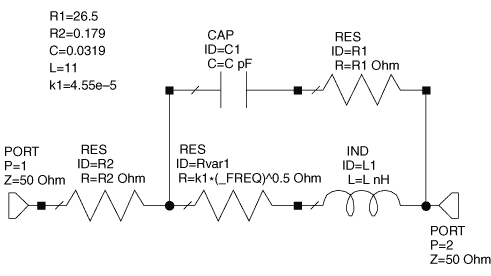
To model our chip inductors, either select the CCIND element from the Lumped Element - Inductor menu or place each individual lumped element for the model onto the schematic. An example chip inductor schematic is shown in Figure 1.

microwave1.gif
Figure 1. Example schematic for a Coilcraft chip inductor

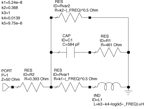
To model our power inductors, each individual lumped element (LVAR, C, R2, R1, RVAR1, RVAR2) for the complete model must be placed into the schematic. An example of a power inductor schematic is shown in Figure 2.

microwave2.gif
Figure 2. Example schematic for a Coilcraft power inductor

After all the lumped elements are placed into the schematic, change the value for each element to match the value in the model table for the specific inductor. If you plan to model different Coilcraft inductors in the same schematic, be sure to rename the individual lumped elements and variables, then update the values from the model table for each inductor.

For a frequency-dependent resistance (RVAR1, RVAR22)

Note: This example uses RVAR1 ( = k1 * sqrt(Frequency)).
  1. Place an ideal resistor on the schematic.
  2. Double click on the resistor to edit the value.
  3. Rename it to identify it as a variable resistor (e.g. "RVAR1").
  4. For the resistance value, enter the equation: k1*(_FREQ)^0.5.
  5. Replace k1 with the value from the model table.

For a frequency-dependent inductance (LVAR)

Note: This element is used in some of our power inductor models.
  1. Place an ideal inductor on the schematic.
  2. Double click on the inductor to edit the value.
  3. Rename it to identify it as a variable inductor (e.g. "LVAR").
  4. For the inductance value, enter the equation: k3-(k4*log(k5*_FREQ)). Note: The "log" function in the following equation is the natural logarithm, base e, not base 10.
  5. Replace k3, k4, and k5 with the values from the model table.

Graphing specific model inductance and Q results

Important! Our models represent de-embedded measurements in which fixture parasitic reactances have been removed. Fixture (or circuit board) parasitic reactances raise the effective impedance (and the effective inductance), lower the self-resonant frequency (SRF), and shift the Q curve. For the most accurate model of our inductors in your specific circuit environment, you must include your circuit board model in the simulation.

Inductance

To view the effective series inductance of the model in a graph:

  1. Right click on the graph name.
  2. Click on "Add Measurement."
  3. In the "Add Measurement" dialog box, select "Linear" as the Meas. Type. and "L_SRL" as the Measurement.
  4. Use your model schematic for the Data Source Name.
  5. Check the "Sweep Proj. Freqs" box, and select the input port to your model.
  6. Click "Add."

Quality factor (Q)

Q values and curves in our data sheets are typically based on measurements using an impedance analyzer in a 50 Ohm environment, giving a 1-port (reflection) measurement result. If Q calculations are to be compared with data sheet values and curves, they should be based on a simulation with one port of the inductor model connected to ground (as shown in Figure 2).

If you are interested in the Q of the inductor in a 2-port series configuration, the additional 50 Ohms impedance of the second port results in a lower simulated Q value than the 1-port configuration. This result is logical considering that the additional 50 Ohms applies to the "Re [Z]" in the denominator of the Q calculation equation.

Q = Im [Z] / Re [Z]

At this time, Microwave Office does not have a Q measurement function. You must enter the equation for Q in the "Output Equations" window.

Im [Z] output equation

  1. Open the "Output Equations" window.
  2. Click on the "Output Equation" icon or select it from the "Add" menu.
  3. Enter a variable name, such as "x".
  4. Select "Linear" as the Meas. Type and "ZIN" as the Measurement.
  5. Select your model schematic for the Data Source Name.
  6. Check the "Sweep Proj. Freqs" box.
  7. Check "Imag" as the Complex Modifier.
  8. Select the input port to your model.
  9. Click "Add."

Re [Z] output equation

  1. Open the "Output Equations" window.
  2. Click on the "Output Equation" icon, or select it from the "Add" menu.
  3. Enter a different variable name than the one used in Im [Z], such as "y".
  4. Select "Linear" as the Meas. Type and "ZIN" as the Measurement.
  5. Use your model schematic for the Data Source Name.
  6. Check the "Sweep Proj. Freqs" box.
  7. Check "Real" as the Complex Modifier.
  8. Select the input port to your model.
  9. Click "Add."

Q equation

  1. Open the "Output Equations" window.
  2. Click on the "Equation" icon or select it from the "Add" menu.
  3. Enter a variable name, such as Q1port".
  4. Complete the equation using your Im [Z] and Re [Z] variables (for example: Q1port = x / y).

To view the Q vs. frequency of the model in a graph

  1. Right click on the graph name, and click "Add Measurement."
  2. In the "Add Measurement" dialog box, select "Output Equations" as the Meas. Type, and "Eqn" as the Measurement.
  3. Use your Q equation variable name for the Data Source Name.
  4. Check "Mag" as the Complex Modifier.
  5. Check the "Sweep Proj. Freqs" box, and select the input port to your model.
  6. Click "Add."